Transistor temperature sensing circuit and voltage regulator having over-temperature protection function
A technology of temperature sensing circuit and transistor, which is applied in the direction of circuit devices, emergency protection circuit devices, parts of emergency protection devices, etc., and can solve the problems of overheating damage of voltage regulators without overtemperature protection function, high temperature damage of generators, etc. problems, to achieve obvious economic and social benefits, reliable work, and low cost
- Summary
- Abstract
- Description
- Claims
- Application Information
AI Technical Summary
Problems solved by technology
Method used
Image
Examples
Embodiment 1
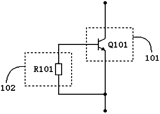
[0044] Such as figure 1 As shown, the basic structure of this transistor temperature sensing circuit includes a transistor detection unit 101 and a temperature correction unit 102. The transistor detection unit has a transistor Q101 sensitive to the temperature range to be measured. The transistor Q101 is an NPN transistor, and the temperature correction unit is a temperature correction unit. The resistor R101, and the temperature correction resistor R101 is connected in parallel with the emitter junction of the transistor Q101, and is used to correct the relationship curve between the on-resistance of the transistor and the sensed ambient temperature.
Embodiment 2
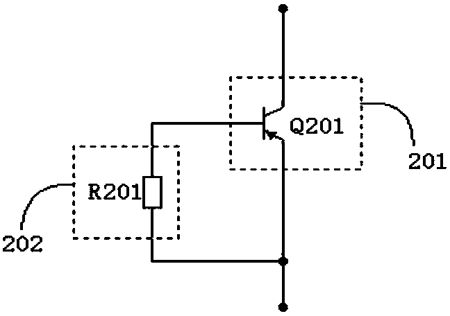
[0046] The embodiment of the present invention provides another transistor temperature sensing circuit, such as figure 2 As shown, its basic structure includes a transistor detection unit 201 and a temperature correction unit 202, the transistor detection unit has a transistor Q201 sensitive to the temperature range to be measured, the transistor Q101 is a PNP transistor, the temperature correction unit is a temperature correction resistor R201, and the temperature correction The resistor R201 is connected in parallel with the emitter junction of the transistor Q201, and is used to correct the relationship curve between the on-resistance of the transistor and the sensed ambient temperature.
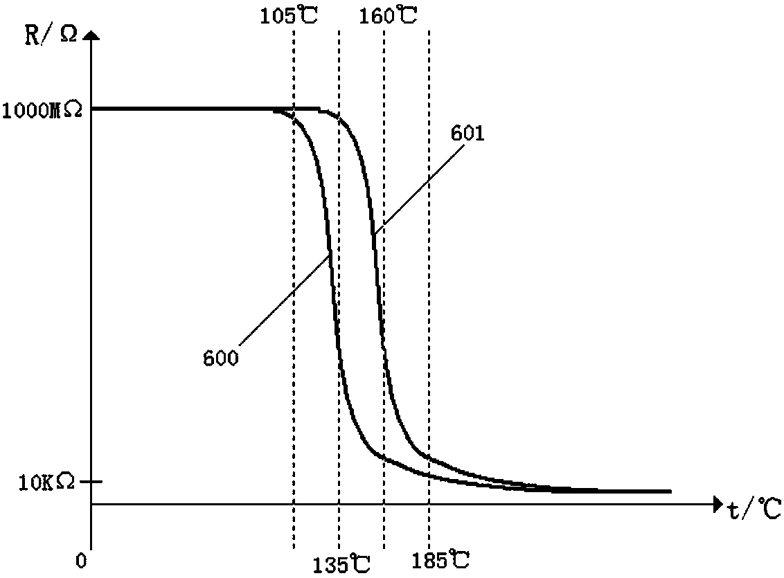
[0047] In the above two embodiments, when the transistor has no base bias current, its leakage current is extremely small at normal temperature (room temperature 15-30° C.), and the leakage resistance between the collector and the emitter is generally above 1000 MΩ. Such as image 3 As ...
Embodiment 3
[0050] The block diagram of the circuit structure of the first voltage regulator with over-temperature protection function provided by the embodiment of the present invention is as follows: Figure 4 As shown, its basic structure includes a sampling unit 11 , a threshold unit 12 , an oscillation unit 14 , a transistor temperature sensing circuit 13 , a power trigger unit 15 and a freewheeling unit 16 .
[0051] The sampling unit 11 is connected to the positive and negative poles of the power supply, the output terminal of the sampling unit is connected to the input terminal of the power trigger unit 15 through the threshold unit 12, and the transistor temperature sensing circuit 13 is connected to the positive pole of the power supply and the power trigger unit. Between the input ends, the oscillation unit 14 is connected to the positive and negative poles of the power supply, the output end of the oscillation unit is connected to the input end of the power trigger unit, the ne...
PUM
 Abstract
Description
Claims
Application Information
 - R&D
- Intellectual Property
- Life Sciences
- Materials
- Tech Scout
- Unparalleled Data Quality
- Higher Quality Content
- 60% Fewer Hallucinations
Browse by: Latest US Patents, China's latest patents, Technical Efficacy Thesaurus, Application Domain, Technology Topic, Popular Technical Reports.
© 2025 PatSnap. All rights reserved.Legal|Privacy policy|Modern Slavery Act Transparency Statement|Sitemap|About US| Contact US: help@patsnap.com


