Ultrasonic driving circuit and fingerprint identification sensor

A driving circuit and ultrasonic technology, applied in character and pattern recognition, acquisition/arrangement of fingerprints/palmprints, instruments, etc., can solve problems such as poor ultrasonic waves and complex structures, and achieve good ultrasonic effects, simple circuit structure, and good effects Effect

Pending Publication Date: 2018-02-02
成都大超科技有限公司
View PDF17 Cites 9 Cited by
  • Summary
  • Abstract
  • Description
  • Claims
  • Application Information

AI Technical Summary

Problems solved by technology

[0004] In order to overcome the technical problems that the structure of the ultrasonic driving circuit of the existing ultrasonic fingerprint recognition s...

Method used


Image

  • Ultrasonic driving circuit and fingerprint identification sensor
  • Ultrasonic driving circuit and fingerprint identification sensor
  • Ultrasonic driving circuit and fingerprint identification sensor

Examples


Embodiment Construction

[0019] In order to make the purpose, technical solutions and advantages of the present invention more clear, the present invention will be further described in detail below in conjunction with the accompanying drawings and implementation examples. It should be understood that the specific embodiments described here are only used to explain the present invention, not to limit the present invention.

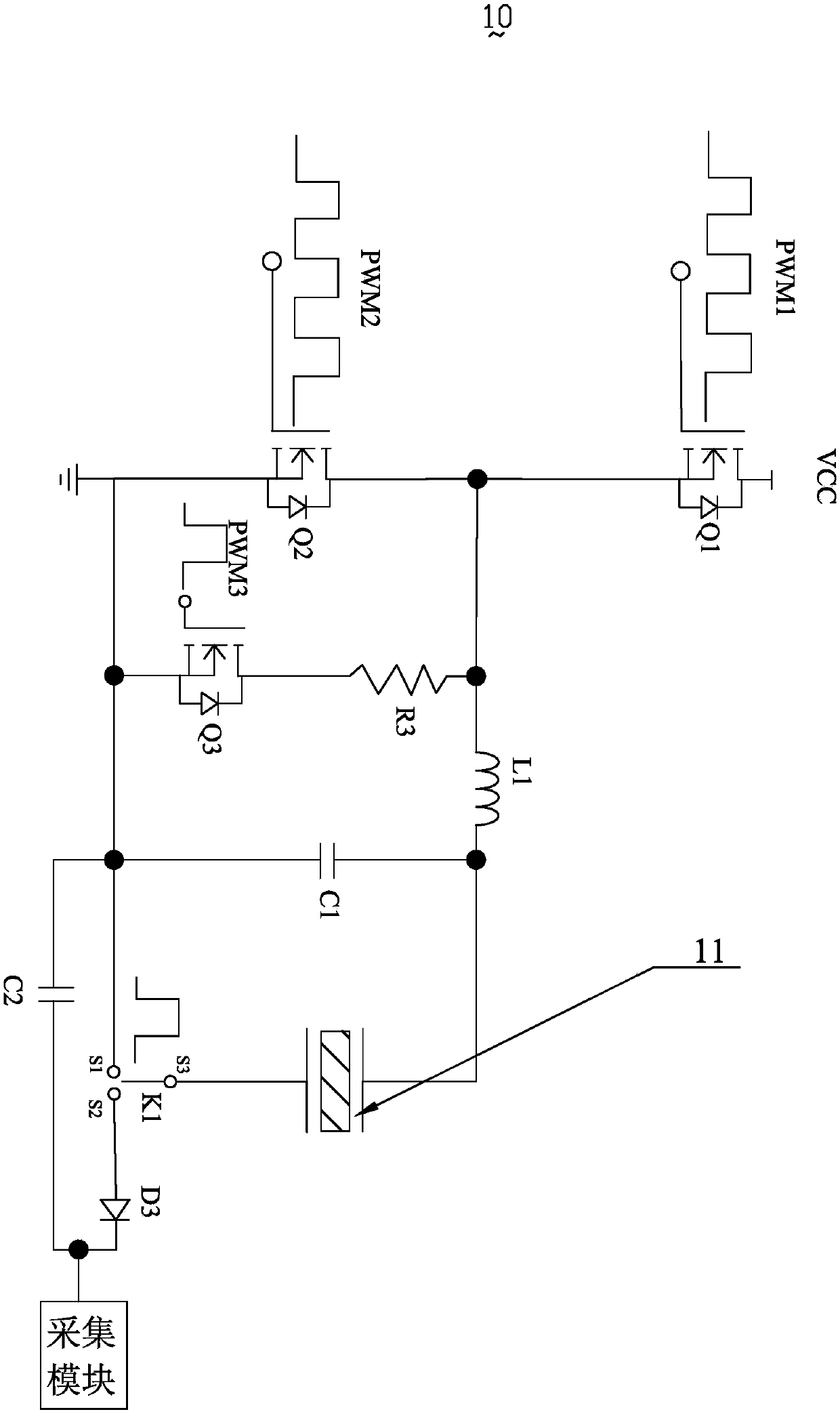
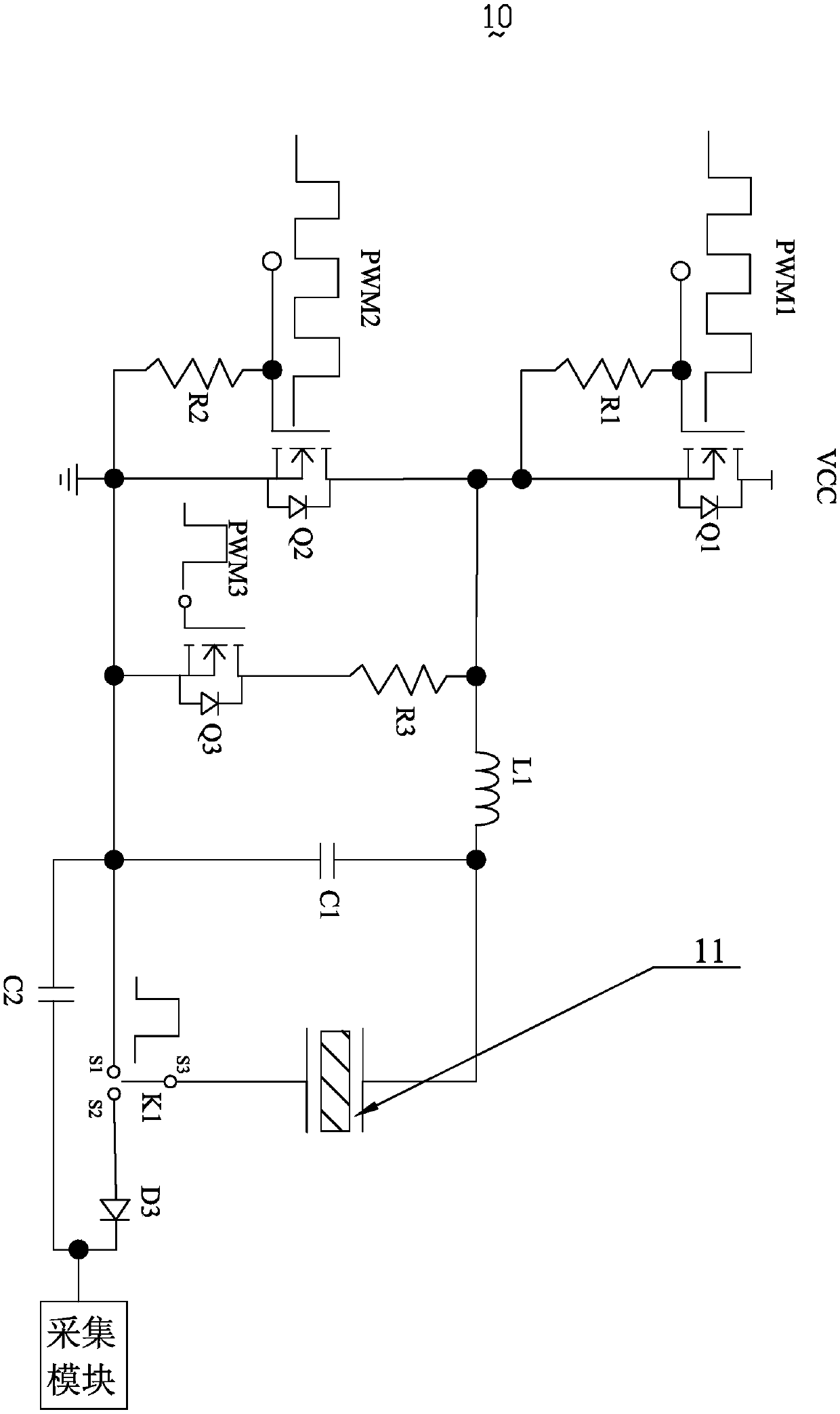
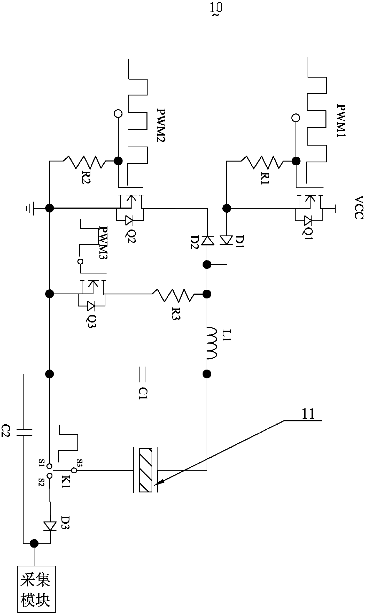
[0020] see figure 1 , the present invention provides an ultrasonic driving circuit 10, which is used to generate ultrasonic waves and receive reflected ultrasonic waves to generate electrical signals and transmit them to the acquisition module.

[0021] The ultrasonic drive circuit 10 includes MOS transistors Q1, Q2, Q3, resistor R3, inductor L1, diode D3, capacitors C1, C2, piezoelectric transducer 11 and switch K1.

[0022] Wherein, the switch K1 is a single-pole double-throw switch, including a pin S1, a pin S2, and a pin S3, and the pin S1 of the switch K1 can be connected to ...


PUM


Abstract

The invention relates to the technical field of ultrasonic fingerprint identification, and particularly relates to an ultrasonic driving circuit and a fingerprint identification sensor. The ultrasonicdriving circuit is characterized in that a drain electrode of an MOS (Metal Oxide Semiconductor) transistor Q1 is electrically connected with an external power supply, a source electrode of the MOS transistor Q1 is electrically connected with a first end of a resistor R3, a first end of an inductor L1 and a drain electrode of an MOS transistor Q2 simultaneously, a source electrode of the MOS transistor Q2 is electrically connected with a source electrode of an MOS transistor Q3, a second end of a capacitor C1, a first end of a capacitor C2 and a pin S1 of a switch K1 simultaneously, the source electrode of the MOS transistor Q2 is grounded, a drain electrode of the MOS transistor Q3 is electrically connected with a second end of the resistor R3, a second end of the inductor L1 is electrically connected with a first end of the capacitor C1 and a top electrode of a piezoelectric transducer simultaneously, a bottom electrode of the piezoelectric transducer is connected with a pin S3 of the switch K1, a pin S2 of the switch K1 is connected with a positive electrode of a diode D3, and a negative electrode of the diode D3 is electrically connected with a second end of the capacitor C2 and an acquisition module simultaneously. The fingerprint identification sensor adopts the ultrasonic driving circuit.

Description

【Technical field】 [0001] The invention relates to the technical field of ultrasonic fingerprint identification, in particular to an ultrasonic drive circuit and a fingerprint identification sensor. 【Background technique】 [0002] Biometric recognition is a technology used to distinguish different biological characteristics, including fingerprints, palm prints, faces, DNA, voice and other recognition technologies. Fingerprints refer to the uneven lines on the skin on the front of the end of a human finger, and the lines are regularly arranged to form different patterns. Fingerprint identification refers to identification by comparing the detailed feature points of different fingerprints. Due to its lifelong invariance, uniqueness and convenience, the application of fingerprint identification is more and more extensive. Due to the good effect of ultrasonic for fingerprint recognition, more and more manufacturers are devoted to the research of ultrasonic fingerprint sensor. ...

Claims


Application Information

Patent Timeline
IPC IPC(8): H02N2/18G06K9/00
CPCH02N2/181G06V40/1306
Inventor 高奇文吴露向勇王开安
Owner 成都大超科技有限公司
Why Eureka
Try Eureka