Optical fiber micro heater and preparation method thereof

A technology of micro-heater and optical fiber, which is applied in the field of optoelectronics, can solve the problems of low heating efficiency and achieve the effect of improving heating efficiency, small size and good flexibility

Active Publication Date: 2019-09-17
SHENZHEN CCT THZ TECH CO LTD
View PDF2 Cites 0 Cited by
  • Summary
  • Abstract
  • Description
  • Claims
  • Application Information

AI Technical Summary

Problems solved by technology

[0004] Based on this, it is necessary to provide an optical fiber micro heater and a preparation method for the problem of low heating efficiency

Method used


Image

  • Optical fiber micro heater and preparation method thereof
  • Optical fiber micro heater and preparation method thereof
  • Optical fiber micro heater and preparation method thereof

Examples


Embodiment Construction

[0037] In order to facilitate the understanding of the present invention, the present invention will be described more fully below with reference to the associated drawings. Preferred embodiments of the invention are shown in the accompanying drawings. However, the present invention can be embodied in many different forms and is not limited to the embodiments described herein. On the contrary, the purpose of providing these embodiments is to make the disclosure of the present invention more thorough and comprehensive.

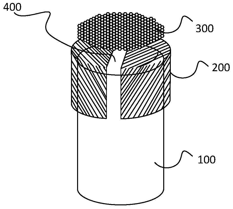
[0038] Such as figure 1 Shown is a schematic diagram of an optical fiber micro heater in an embodiment. The fiber optic micro-heater is used to realize rapid heat transfer, and may include an optical fiber 100 , a metal electrode 200 and a graphene layer 300 . Wherein, the optical fiber 100 has a light-emitting end face 400 for receiving and transmitting optical signals to the light-emitting end face 400; the metal electrode 200 covers the end of the optical...


PUM

PropertyMeasurementUnit
diameteraaaaaaaaaa
thicknessaaaaaaaaaa
diameteraaaaaaaaaa

Abstract

The present invention relates to an optical fiber micro-heater, comprising: an optical fiber, which is provided with a light exit end surface and which is used for receiving and transmitting an optical signal to the light exit end surface; metal electrodes, which cover an end portion of the optical fiber that is provided with the light exit end surface; a graphene layer, which covers the light exit end surface of the optical fiber which is covered by the metal electrodes. The present invention further relates to a preparation method for an optical fiber micro-heater, comprising: preparing a pair of metal electrodes on an optical fiber tangential to the light exit end surface; providing a metal base that is covered by graphene, and transferring the graphene from the metal base into deionized water to form a graphene thin film; passing the light exit end surface of the optical fiber that is manufactured with metal electrodes through the graphene thin film; extracting and drying the optical fiber that passes through the graphene thin film. The quick transfer of heat may be achieved due to the excellent heat conduction performance of graphene, thus increasing heating efficiency; moreover, the heating of a designated place within a small range may be achieved by the optical fiber micro-heater due to the small size and good flexibility of the optical fiber.

Description

technical field [0001] The invention relates to the field of optoelectronic technology, in particular to an optical fiber micro heater and a manufacturing method. Background technique [0002] At present, with the wide application of optical fiber in the field of optoelectronic technology, the preparation of optical fiber and related technologies are becoming more and more mature. Among them, the preparation of optical fiber thermal control devices is a very important technology. [0003] Traditional optical fiber thermal control devices use metal electrodes as heat sources, but metal electrodes have a great influence on light transmission, so the heating efficiency is relatively low when metal electrodes are used as heat sources. And for the optical fiber thermal control device with a very small heating area, the existing temperature measurement methods, such as infrared thermometers, thermocouples, etc., cannot accurately measure the actual temperature. This directly affe...

Claims


Application Information

Patent Timeline
Patent Type & Authority Patents(China)
IPC IPC(8): H05B3/14
Inventor 李程郑渚杨彬徐飞丁庆
Owner SHENZHEN CCT THZ TECH CO LTD
Why Eureka
Try Eureka