Elastic barb medical bone screw

A bone screw and elastic technology, applied in the field of elastic barb medical bone screws, can solve the problems of complex load failure, insufficient screw tooth rigidity, internal thread damage, etc., to improve installation stability, improve installation accuracy, and not easy to misplace Effect

Pending Publication Date: 2018-02-06
GUANGDONG UNIV OF TECH
View PDF1 Cites 3 Cited by
  • Summary
  • Abstract
  • Description
  • Claims
  • Application Information

AI Technical Summary

Problems solved by technology

From the perspective of biomechanics and engineering, the stability of the external nail is the contact problem of the bone-external nail interface. In the traditional mechanical field, the failure and loosening of the external nail is the moment provided by the friction between the external nail and the implant. The torque smaller than the instantaneous vibration will cause the outer nail to slide, and the complex load of the reciprocating vibration machine will eventually lead to failure.
Another type of failure is related to the stiffness of the outer nail. The axial load (pullout force) is loaded along the axis of the outer nail. The screw tooth deforms and fails due to insufficient stiffness, or the internal thread of the implanted material is damaged.
[0004] In order to solve the problem that the outer nail is easy to loosen, the Chinese invention patent application number 201210345780.4 discloses an outer nail with V-shaped elastic barbs, thereby enhancing the pull-out resistance and radial stability of the outer nail. It is difficult to remove after the nail is fixed, and it is harmful to the human body if it exists in the body for a long time

Method used


Image

  • Elastic barb medical bone screw
  • Elastic barb medical bone screw
  • Elastic barb medical bone screw

Examples


Embodiment 1

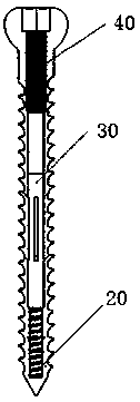
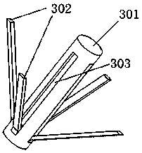
[0041] Such as figure 1 and figure 2 As shown, the present embodiment provides an elastic barb medical bone screw, including an outer nail 10 and an elastic barb member 30, and also includes an elastic reset member and an inner nail 40. The outer nail 10 is provided with an inner cavity, and the elastic reset member is located on At the bottom of the inner cavity of the outer nail 10, the elastic barb part 30 includes a mounting post 301 and a shrapnel 302. The elastic barb part 30 is arranged in the inner cavity of the outer nail 10. The upper end of the elastic reset part contacts the lower end of the mounting post 301, and the lower end of the inner nail 40 In contact with the upper end of the mounting post 301, the mounting post 301 is provided with a shrapnel receiving groove 303, one end of the shrapnel 302 is connected to the shrapnel receiving groove 303, the other end of the shrapnel 302 is ejected relative to the mounting post 301, and the ejection opening of the sh...

Embodiment 2

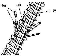
[0050] Such as image 3 As shown, this embodiment provides an elastic barb medical bone screw. This embodiment is similar to Embodiment 1, except that the elastic barb component 30 in this embodiment includes a mounting column 301 and four strip-shaped elastic pieces 302. The shrapnel 302 are symmetrically distributed around the axis of the mounting column 301. The four shrapnels 302 are connected to the shrapnel receiving groove 303 at the same radial section of the mounting post 301. The adjacent shrapnel 302 are in the axial direction of the mounting post 301. projections are perpendicular to each other.

[0051] The shrapnel are symmetrically distributed in the center of the mounting column 301 and fixed in the bone tissue. The force in the radial direction of the bone screw is balanced, and it is not easy to be misplaced, which improves the installation accuracy of the bone screw and reduces the difficulty of installation.

[0052] Four elongated elastic pieces 302 are a...

Embodiment 3

[0055] Such as image 3 As shown, this embodiment provides a medical bone screw with elastic barbs. This embodiment is similar to Embodiment 2, except that the included angle between the axis of the ejection hole 101 and the axis of the outer nail 10 in this embodiment is 45°.

[0056] The contact area between the elastic piece 302 and the bone tissue is consistent, and the force applied to the elastic piece 302 is consistent. The pop-up angle of the elastic piece 302 is 45°, and the sum of the radial and lateral force components of the mounting column 301 generated by the elastic piece 302 is the largest. At this time, the anti-rotation and pull-out resistance The overall effect of the load capacity is the best.

[0057] Preferably, the surfaces of the outer nail 10 and the shrapnel 302 are plated with titanium or titanium alloy.


PUM


Abstract

The invention discloses an elastic barb medical bone screw which comprises an outer nail and elastic barb components and is characterized by also comprising elastic reset components and an inner nail;the outer nail is provided with an inner cavity; the elastic reset components are arranged at the bottom of the inner cavity of the outer nail; each elastic barb component comprises a mounting columnand an elastic piece and is arranged in the inner cavity of the outer nail; the upper end of each elastic reset component is in contact to the lower end of the corresponding mounting column; the lower end of the inner nail is in contact to the upper ends of the mounting columns; each mounting column is provided with an elastic piece receiving groove; one end of each elastic piece is connected with the corresponding elastic piece receiving groove; the other end of each elastic piece is popped up relative to the corresponding mounting column; elastic piece popup openings face the inner nail; the side wall of the inner cavity is provided with popup holes through which the corresponding elastic pieces are propped up, and the positions and amounts of the popup holes correspond to the positionsand amounts of the elastic pieces. The bone screw provided by the invention is firm to mount and convenient to disassemble and take out.

Description

technical field [0001] The invention relates to a bone screw, in particular to an elastic barb medical bone screw. Background technique [0002] Fracture is a kind of acute clinical problem that traumatologists face daily. Single or reciprocating overload is the main cause of fracture, causing predictable soft tissue damage. The fracture surface is broken and separated rapidly, forming a gap (space) Acupuncture phenomenon), causing different degrees of damage to soft tissue, once a fracture occurs, timely and effective fixation treatment must be carried out to prevent secondary damage. [0003] Bone screws are implants that are in direct contact with bone, and the stability of their combination with bone material is the most critical factor for the success of the entire fracture treatment operation. The root cause of the loosening and pulling out of the external nail is the failure of the internal and external threaded connection between the external nail and the bone. The ...

Claims


Application Information

Patent Timeline
Patent Type & Authority Applications(China)
IPC IPC(8): A61B17/68A61B17/86
CPCA61B17/683A61B17/8625A61B17/864A61B2017/8655
Inventor 王成勇周绍波隋建波冯文强郭紫莹
Owner GUANGDONG UNIV OF TECH
Why Eureka
Try Eureka