LED measurement clamp

A technology for measuring fixtures and splints, which is applied in the direction of measuring electricity, measuring devices, measuring electrical variables, etc., can solve the problems of inaccurate position of contact probes, unstable fixture test results, and long time to replace LEDs, etc., to achieve convenient operation, The effect of reasonable fixture space design and long service life

Pending Publication Date: 2018-02-06
深圳市奥谱特科技有限公司
View PDF0 Cites 1 Cited by
  • Summary
  • Abstract
  • Description
  • Claims
  • Application Information

AI Technical Summary

Problems solved by technology

Due to the relatively imperfect structural design, inaccurate fixture fixing position, inaccurate contact probe position, and inconvenient mechanical operation of

Method used


Image

  • LED measurement clamp
  • LED measurement clamp
  • LED measurement clamp

Examples


Embodiment Construction

[0035] The following will clearly and completely describe the technical solutions in the embodiments of the present invention with reference to the accompanying drawings in the embodiments of the present invention. Obviously, the described embodiments are only some, not all, embodiments of the present invention. Based on the embodiments of the present invention, all other embodiments obtained by persons of ordinary skill in the art without creative work, any modifications, equivalent replacements, improvements, etc., shall be included in the protection scope of the present invention Inside.

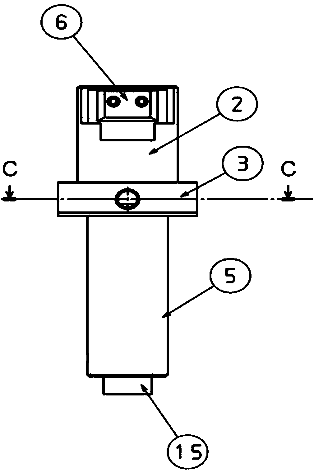
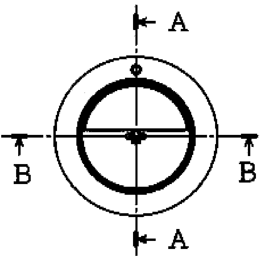
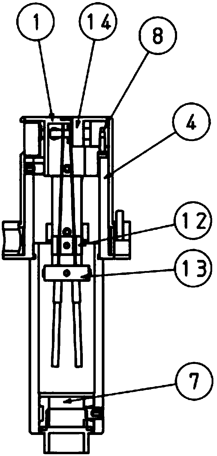
[0036] Such as Figure 1-9As shown, the LED measurement fixture of the present invention includes an LED placement substrate 1 for fixing the LED, a probe, a fixed clamping mechanism for fixing and clamping the LED, and is used to control the rise or fall of the probe and make the probe vertically The probe control mechanism that contacts or is away from the LED conductive contact in the...


PUM


Abstract

The invention discloses an LED measurement fixture, which includes an LED placement substrate, a probe, a fixed clamping mechanism, a probe control mechanism, and a conductive mechanism connected with the probe; the fixing mechanism clamps and fixes the LED on the LED placement substrate, The probe control mechanism makes the probe rise or fall, and makes the probe contact or stay away from the LED conductive contact in the vertical direction. The conductive mechanism makes the probe conduct electricity, and the tester system completes and tests related parameters. The LED measurement jig of the present invention has the advantages of 1. easy operation and long service life; 2. accurate position control of the LED, precise position of the contact probe, and strong stability; 3. separate control of the probe up and down from the control of the LED splint, so that the LED placement process 4. The LED parameters tested by the fixture have strong stability; 4. The time to replace the LED is short; 5. The fixture space design is reasonable and the replacement of parts is convenient.

Description

technical field [0001] The invention relates to the technical field of measuring electronic components, in particular to an LED measuring fixture. Background technique [0002] LED (Light Emitting Diode) has been widely promoted and applied because it meets the development requirements of energy saving and environmental protection in today's society. During the production process of LEDs, it is necessary to use fixtures to measure LEDs, and the stability of LED fixtures directly affects the stability of test results. The fixture is used very frequently during the generation process, so the service life of the fixture has become a very important indicator. Due to the relatively imperfect structural design, inaccurate fixture fixing position, inaccurate contact probe position, and inconvenient mechanical operation of traditional fixtures, the test results of the fixture are unstable, the service life is short, the operation is inconvenient, and the LED replacement time is lon...

Claims


Application Information

Patent Timeline
IPC IPC(8): G01R1/04G01R1/073
CPCG01R1/0425G01R1/07392
Inventor 宫庆良黄安平张国军陈培宏
Owner 深圳市奥谱特科技有限公司
Why Eureka
Try Eureka