Pixel circuit and driving method thereof
A technology of a pixel circuit and a driving method, applied in the display field, can solve the problems of increasing the difficulty of the process, affecting the symmetry and matching state of other main devices, and achieve the effects of improving stability, improving the degree of screen flicker, and increasing the holding ability.
- Summary
- Abstract
- Description
- Claims
- Application Information
AI Technical Summary
Problems solved by technology
Method used
Image
Examples
Embodiment 1
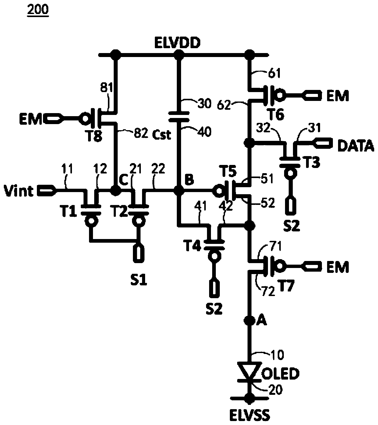
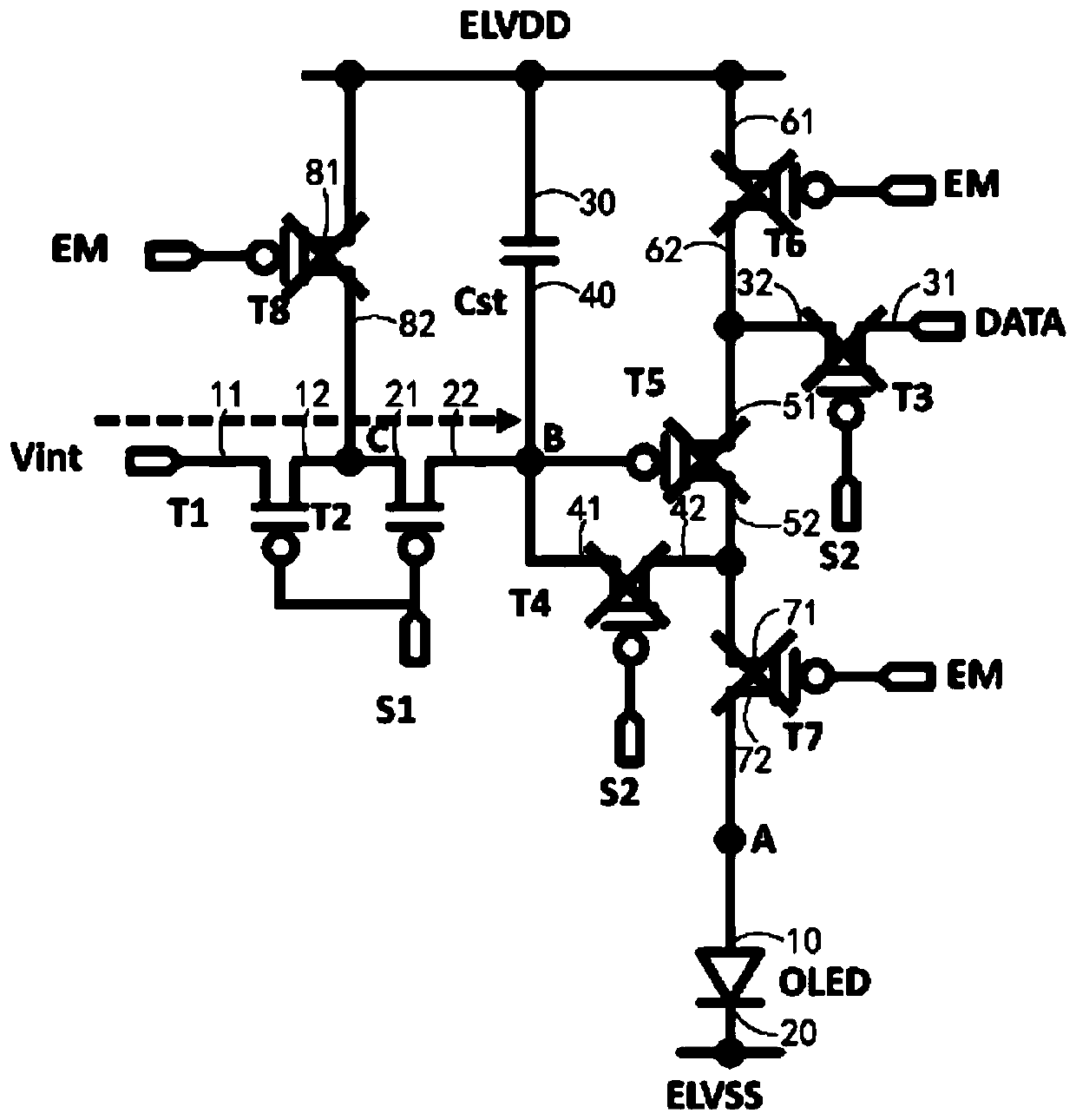
[0052] figure 2 is a schematic structural diagram of a pixel circuit according to Embodiment 1 of the present invention. According to this embodiment, the circuit 200 includes: a first transistor T1, whose first terminal 11 is connected to the input voltage Vint; a second transistor T2, whose first terminal 21 is electrically connected to the second terminal 12 of the first transistor T1, the first The control ends of the transistor T1 and the second transistor T2 are electrically connected to the first scan signal S1; the third transistor T3, the first end 31 of which is electrically connected to the data signal DATA; the fourth transistor T4, whose first end 41 is electrically connected to the second transistor The second terminal 22 of T2, the control terminals of the third transistor T3 and the fourth transistor T4 are electrically connected to the second scanning signal S2; the fifth transistor T5, the first terminal 51 of which is electrically connected to the second te...
Embodiment 2
[0065] Figure 4 is a schematic structural diagram of a pixel circuit 400 according to Embodiment 2 of the present invention. The difference between the pixel circuit 400 of this embodiment and the pixel circuit 200 of the first embodiment is that it further includes a ninth transistor T9, the first terminal 91 of the ninth transistor T9 is electrically connected to the second terminal of the fourth transistor T4 42 and the second terminal 82 of the eighth transistor T8, the second terminal 92 thereof is electrically connected to the second terminal 52 of the fifth transistor T5, and the control terminal thereof is electrically connected to the second scanning signal S2.
[0066] Continue to refer to Figure 3 for the Figure 4 The timing diagram of the driving method of the pixel circuit shown, during the reset period, the first scan signal S1 is at low level, the second scan signal S2 and the control signal EM are at high level, at this time the first transistor T1 and the s...
Embodiment 3
[0070] Figure 5 is a schematic structural diagram of a pixel circuit 500 according to Embodiment 3 of the present invention. The pixel circuit 500 of this embodiment differs from the pixel circuit 200 of the first embodiment above in that it further includes a tenth transistor T10, the first terminal 101 of which is electrically connected to the second terminal 72 of the seventh transistor T7, and the second The terminal 102 is electrically connected to the input voltage Vint, and its control terminal is electrically connected to the third scanning signal S3. The tenth transistor T10 may be used to implement a reset function of a light emitting diode (eg, OLED).
[0071] refer to Figure 6 for Figure 5 In the timing diagram of the driving method of the pixel circuit shown, a release period is added to the circuit due to the addition of the third scanning signal S3.
[0072] During the reset period, the first scanning signal S1 is at low level, the second scanning signal ...
PUM
 Abstract
Description
Claims
Application Information
 - R&D
- Intellectual Property
- Life Sciences
- Materials
- Tech Scout
- Unparalleled Data Quality
- Higher Quality Content
- 60% Fewer Hallucinations
Browse by: Latest US Patents, China's latest patents, Technical Efficacy Thesaurus, Application Domain, Technology Topic, Popular Technical Reports.
© 2025 PatSnap. All rights reserved.Legal|Privacy policy|Modern Slavery Act Transparency Statement|Sitemap|About US| Contact US: help@patsnap.com


