Gantry type numerically controlled cutting machine

A cutting machine, gantry technology, applied in metal processing equipment, welding equipment, manufacturing tools, etc., can solve the problems of inaccurate cutting position of the plate, damage to the health of users, shortened service life, etc., and achieve stable and stable structural design and automation. High-level, wide-ranging effects

Inactive Publication Date: 2018-02-09
JIANGSU ZHENGHE HEAVY IND CO LTD
View PDF11 Cites 6 Cited by
  • Summary
  • Abstract
  • Description
  • Claims
  • Application Information

AI Technical Summary

Problems solved by technology

[0004] Most of the common CNC cutting machines are cutting because the walking wheels will gradually deviate from the track during the walking process, so the cut plates will have the disadvantages of inaccurate cutting positions and errors; in addition, most of these CNC cutting machines are It does not have a water spray device. When the staff uses the cutting machine, a large amount of metal dust will be generated, which will not only cause a lot of pollution, but also damage the health of the users.
Not only that, but saw blades generate a lot of heat when cutting steel, reducing service life

Method used


Image

  • Gantry type numerically controlled cutting machine
  • Gantry type numerically controlled cutting machine
  • Gantry type numerically controlled cutting machine

Examples


Embodiment 1

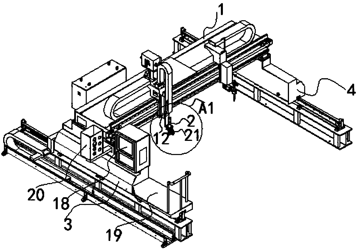
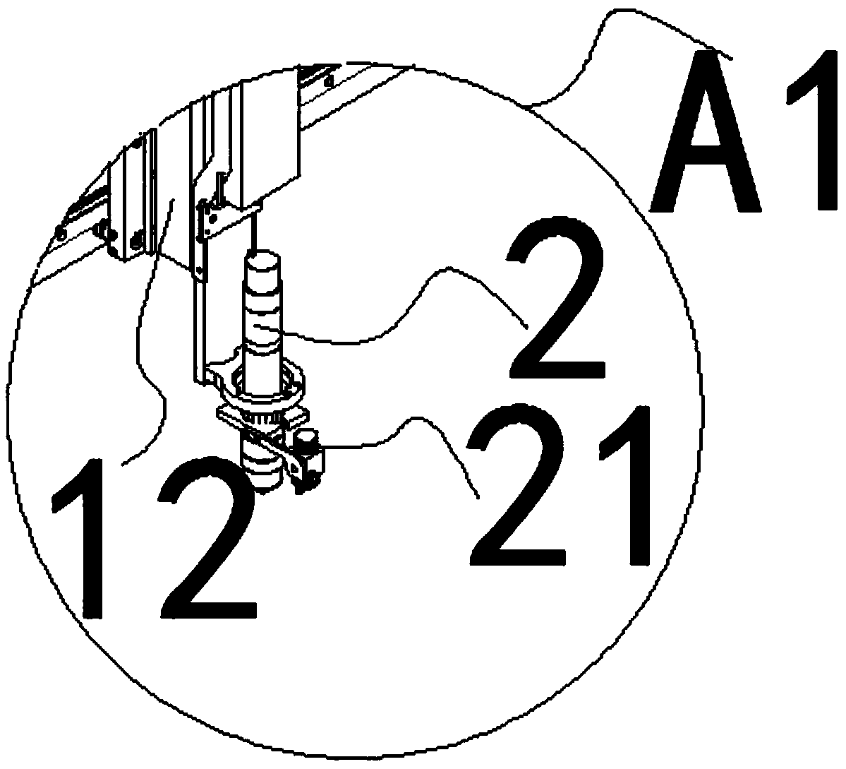
[0046] Embodiment 1: a kind of gantry type numerical control cutting machine, as Figure 1-Figure 10 As shown, it is used to cut plates, including a frame, a beam 1 and at least one cutting torch 2, the frame includes a main frame 3 and a sub-frame 4, and the two ends of the beam are respectively connected to the main frame and the sub-frame , the cutting gun is installed on the beam, and the length direction of the frame is defined as the longitudinal direction, and the cutting machine also includes a longitudinal drive mechanism for driving the frame to move longitudinally, a transverse drive mechanism for driving the cutting gun to move laterally, and a drive mechanism for driving the cutting gun to lift Lifting mechanism and spraying mechanism;

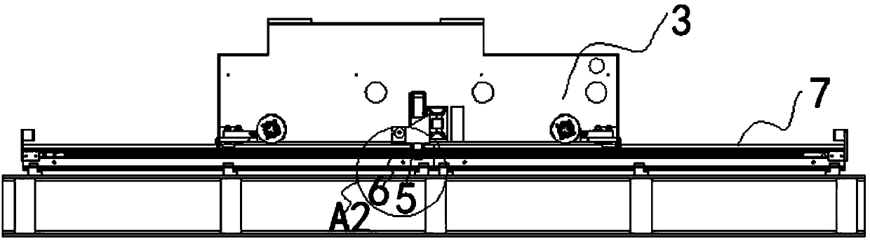
[0047] The longitudinal driving mechanism is arranged on the frame, and the longitudinal driving mechanism includes a first gear 5, a first rack 6, a first motor and a first track 7, and the first gear and the first rack are meshe...

Embodiment 2

[0063] Embodiment 2: a kind of gantry type numerical control cutting machine, as Figure 11-Figure 12 As shown, its structure is basically the same as that of Embodiment 1, except that the cutting torch is a rotary head cutting torch 17.

[0064] The gun head of the rotary head cutting gun rotates left and right in the vertical plane.

[0065] The gun head of the rotary head cutting gun rotates around the vertical circle.

[0066] The working principle of the present invention is as follows:

[0067] In the present invention, the workpiece to be cut is placed on the workbench, the cutting machine is started, and under the control of the control system, the first motor of the longitudinal drive mechanism drives the beam through the rack and pinion structure to drive the cutting torch to move longitudinally along the first track, and the horizontal drive The second motor of the mechanism drives the mounting seat of the cutting gun to drive the cutting gun to move laterally thr...


PUM


Abstract

The invention discloses a gantry type numerically controlled cutting machine which comprises a rack, a cross beam and at least one cutting gun. The rack comprises a primary rack and an auxiliary rack.The cutting machine also comprises a longitudinal driving mechanism, a transverse driving mechanism, a lifting mechanism and a spraying mechanism; the longitudinal driving mechanism is arranged on the rack and comprises a first gear, a first rack, a first motor and a first rail; the transverse driving mechanism is arranged on the cross beam and comprises a second gear, a second rack, a second motor and a second rail; the lifting mechanism is arranged on the cross beam and is fixedly connected to a mounting seat of each of the cutting guns; the lifting mechanism comprises a lifting unit provided with a driving structure; the spraying mechanism is arranged on the rack and comprises a water tank and a shower nozzle. The gantry type numerically controlled cutting machine disclosed by the invention is compact in structure and simple to operate. In addition, the gantry type numerically controlled cutting machine also has the characteristics of being high in speed, stable in quality and thelike.

Description

technical field [0001] The invention relates to a cutting equipment technology, in particular to a gantry type numerical control cutting machine. Background technique [0002] CNC cutting machine is a fully automatic equipment that uses digital programs to drive the movement of the machine tool. When the machine tool moves, the cutting tool that comes with it will cut the plate (ferrous metal and non-ferrous metal). It can realize cutting of any shape. CNC cutting machine has the advantages of high automation, easy operation, high efficiency and high precision, so it is more and more widely used in machining, advertising production and other industries. [0003] Existing CNC cutting machines mainly include flame cutting machines and plasma cutting machines. Flame cutting machines rely on combustible gas to generate high temperature during combustion, and use high-temperature and high-pressure flames to directly melt and separate the cutting body to complete the cutting proce...

Claims


Application Information

Patent Timeline
Patent Type & Authority Applications(China)
IPC IPC(8): B23K28/02
CPCB23K28/02
Inventor 卢锋
Owner JIANGSU ZHENGHE HEAVY IND CO LTD
Why Eureka
Try Eureka