
An evaporation tube, a combustion chamber, and an engine with a built-in swirler at the outlet

A technology of returning combustion chamber and evaporating tube, applied in the field of engine and combustion chamber, can solve the problems of inability to change the oil and gas mixture, flameout, inability to improve the residence time of high temperature gas, etc., to widen the stable working range, increase the airflow speed, and improve the fuel The effect of spatial distribution uniformity

Active Publication Date: 2020-08-14
INST OF ENGINEERING THERMOPHYSICS - CHINESE ACAD OF SCI
View PDF7 Cites 0 Cited by
  • Summary
  • Abstract
  • Description
  • Claims
  • Application Information

AI Technical Summary

Problems solved by technology

These schemes basically improve the mixing effect and combustion efficiency by increasing the heat exchange area of ​​fuel and air in the evaporator tube, but these measures are inside the evaporator tube and cannot change the oil-gas mixture. There is no stable backflow downstream of the evaporator tube outlet. This key feature of the gas zone cannot improve the residence time of high-temperature gas in the downstream, and it is prone to flameout in low-load conditions

Method used


Image

  • An evaporation tube, a combustion chamber, and an engine with a built-in swirler at the outlet
  • An evaporation tube, a combustion chamber, and an engine with a built-in swirler at the outlet
  • An evaporation tube, a combustion chamber, and an engine with a built-in swirler at the outlet

Examples


Embodiment Construction

[0031] In order to make the object, technical solution and advantages of the present invention clearer, the present invention will be further described in detail below with reference to the accompanying drawings and examples.

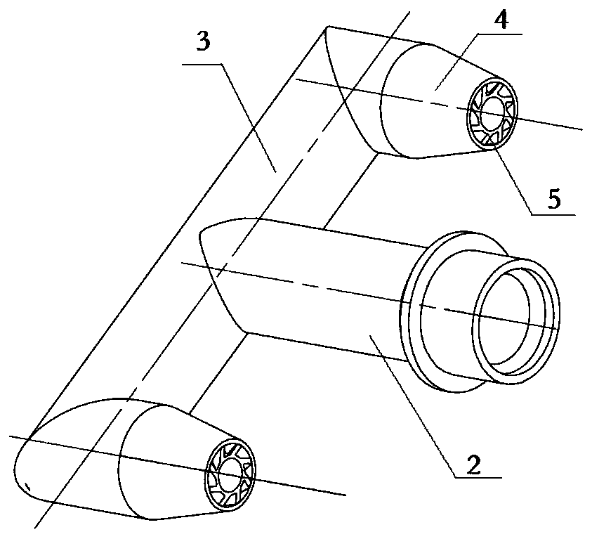
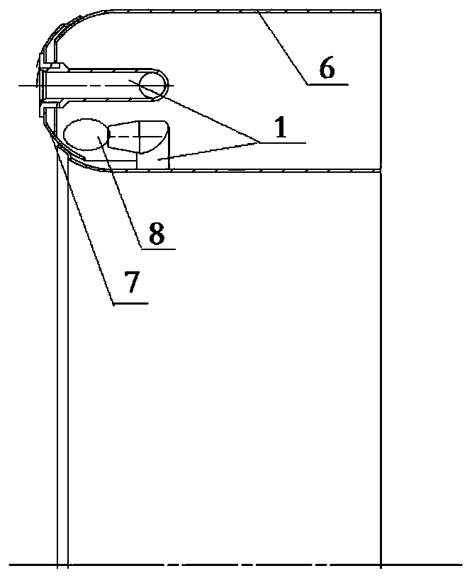
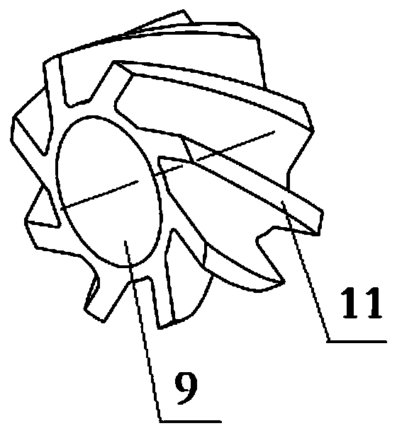
[0032] Such as figure 1 As shown, the evaporating tube with a built-in cyclone in the outlet of the present invention includes an evaporating tube inlet section 2, an evaporating tube middle section 3, an evaporating tube outlet section 4, an evaporating tube inlet section 2, an evaporating tube middle section 3, and an evaporating tube that are connected in sequence. Pipe outlet section 4 three sections constitute L type or T type ( figure 1 Shown in is the T-shaped evaporation tube structure). A cyclone 5 is built in at the outlet of the evaporating tube outlet section 4, such as image 3 As shown, the swirler 5 includes a central passage 9 and a swirl passage arranged on the peripheral periphery of the central passage by a plurality of swirl vanes ...


PUM


Abstract

The invention provides an evaporator with a cyclone in an outlet. The cyclone comprises a center channel, and a cyclone channel arranged at the outer periphery of the center channel; and an evaporation tube with the structure is adopted, on the one hand, the cyclone effect of air can be used for accelerating crushing and atomization of fuel drops, so that the fuel atomization quality is improved,and the fuel and air mixing effect is improved; and on the other hand, a stable reflux area with a certain size can be formed in a downstream area of an outlet of the evaporation tube, so that the stop time is prolonged, meanwhile, the combustion stability of flame at the head part of a combustion chamber of the evaporation tube is improved, and the lean oil flameout limit of the combustion chamber is reduced. The evaporator has the following advantages: the advantages of simple structure of the combustion chamber of a traditional evaporation tube and stable flame of the cyclone with the center channel and the cyclone channel are combined, so that the fuel atomization quality and the flame stability of the combustion chamber of the evaporation tube are greatly improved. The evaporator withthe cyclone in the outlet can be used for a micro aircraft engine and a ground gas turbine combustion chamber.

Description

technical field [0001] The invention belongs to the field of micro-miniature aero-engines and ground gas turbine combustion chambers, and in particular relates to an evaporation tube with a built-in swirler at the outlet, a combustion chamber and an engine containing the evaporation tube, which can effectively improve the mixing effect of fuel and air and increase the flame stability. Background technique [0002] Combustion chambers using evaporator tubes are widely used in micro and small power equipment such as aero engines and ground gas turbines, such as a series of products such as Dutch AMT, British Rolls-Royce, and Artesjet. Compared with the normal combustion chamber, this kind of combustion chamber has the advantages of simple structure and low cost. The evaporation tube is generally matched with the direct injection nozzle, but due to the lack of a special oil-gas mixing device, the fuel atomization effect is poor, resulting in insufficient combustion, and Since ...

Claims


Application Information

Patent Timeline
Patent Type & Authority Patents(China)
IPC IPC(8): F23R3/32F23R3/38
CPCF23R3/32F23R3/38
Inventor 刘富强卢海涛穆勇杨金虎刘存喜胡春艳徐纲朱俊强
Owner INST OF ENGINEERING THERMOPHYSICS - CHINESE ACAD OF SCI
Learn More