
A space spiral motion device

A technology of spiral motion and space, applied in the direction of measuring devices, instruments, measuring instrument components, etc., can solve the problems of fixed motion parameters, high degree of flexibility, complex drive structure, etc., and achieve low manufacturing and processing costs and a high degree of flexibility The effect of high, simple driving structure

Active Publication Date: 2019-10-11
CHONGQING JIANSHE IND GRP
View PDF6 Cites 0 Cited by
  • Summary
  • Abstract
  • Description
  • Claims
  • Application Information

AI Technical Summary

Problems solved by technology

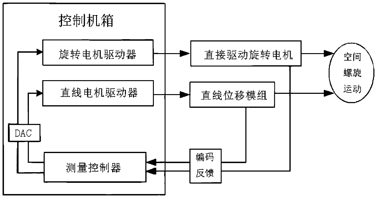
[0003] The present invention aims at the problem that the motion parameters of the spiral motion device are fixed, the degree of flexibility is low, and the drive structure is complicated in the prior art, and it provides a space spiral motion device, through which the combination of arbitrary rotation motion and linear motion can be realized, By setting different programs to precisely control the speed ratio of linear motion and rotary motion, helical motion with different motion parameters is realized, with a high degree of flexibility. At the same time, direct motor drive technology is used to avoid transmission errors, and one-dimensional linear motion at different speeds can be realized. Motion or rotary motion, and the compound of linear motion and rotary motion at different speeds can also be realized at the same time, that is, space spiral motion

Method used


Image

  • A space spiral motion device
  • A space spiral motion device
  • A space spiral motion device

Examples


Embodiment Construction

[0027] Embodiments of the present invention will be described in further detail below in conjunction with the accompanying drawings.

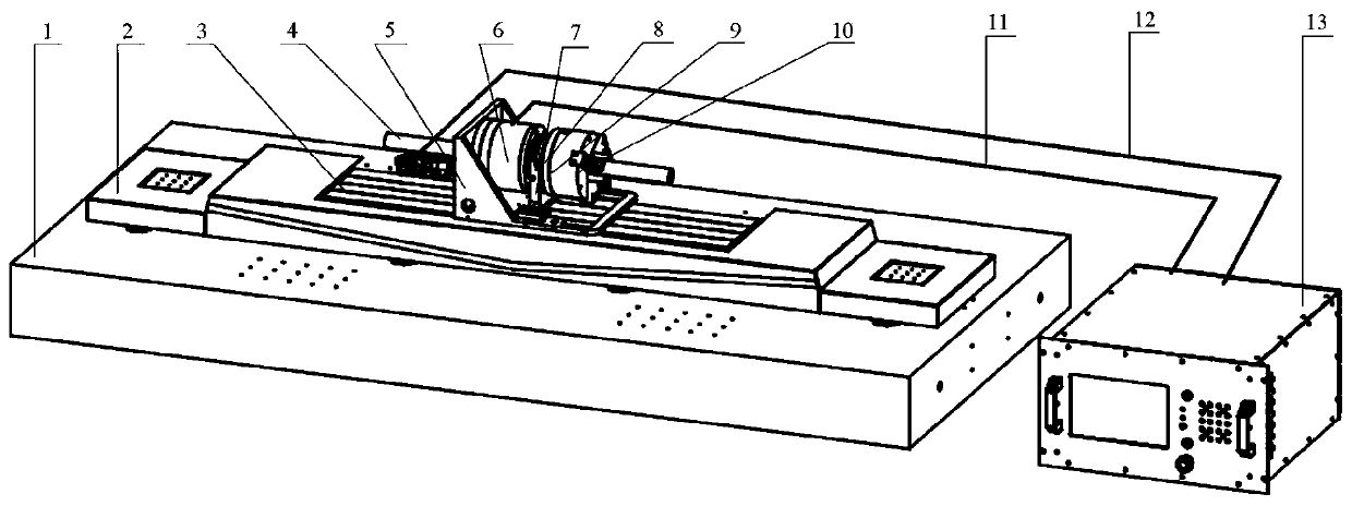
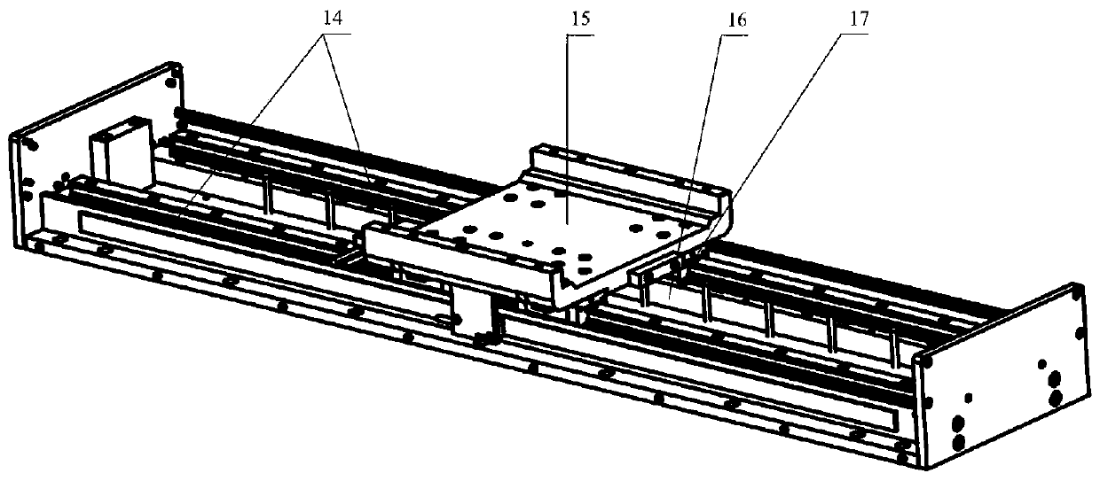
[0028] as attached figure 1 As shown, a space spiral movement device includes a base 1 and a control cabinet 13 arranged on one side of the base 1, and also includes a linear displacement module 3 fixedly installed on the base 1, and one part of the linear displacement module 3 The side is connected with the first power supply control line 12 connected to the corresponding interface of the control cabinet 13, and the linear displacement module 3 realizes the linear reciprocating motion of the device through the program set by the control cabinet 13;

[0029] The rotating mechanism placed above the linear displacement module 3, the rotating mechanism reciprocates linearly with the linear displacement module 3, and the second power control line 11 connected to the corresponding interface of the control cabinet 13 is connected to the rotating mech...


PUM


Abstract

The invention discloses a spatial helical motion device including a base table and a control case and also including a linear displacement module. One side of the linear displace module is provided with a first power control line. Linear reciprocating motion of the device is realized through a program set for the control case. A rotary mechanism disposed above the linear displacement module moveslinearly in a reciprocating manner along with the linear displacement module. The rotary mechanism is provided with a second power control line. The rotation motion of the device is realized through the program set for the control case. The motion direction of the linear displacement module is parallel to the axial direction of the rotary mechanism. When the rotary mechanism moves linearly in a reciprocating manner along with the linear displacement module, the rotary mechanism enables the rotation motion of the device at the same time. The simultaneous motion of the linear displacement moduleand the rotary mechanism enables the spatial helical motion. According to the invention, helical motion of fixed parameters and variable parameters can be realized. The flexibility is high, the drivestructure is simple and collected data accuracy is high. Therefore, requirements for the helical motion device of different motion parameters are met.

Description

technical field [0001] The invention relates to the technical field of screw motion devices, in particular to a space screw motion device. Background technique [0002] In the field of machinery manufacturing and testing, it is often necessary to use a kinematic device that combines rotational motion and linear motion at the same time. For example, in thread processing, thread parameter detection, and other tasks, kinematic devices that combine rotational motion and linear motion are used. , at present, the mechanism devices that realize compound motion are all realized by mechanical transmission. Most of the intermediate transmission parts (such as belts, gears, lead screws, etc.) are used between the motor and the actuator. It will bring a certain amount of transmission error, not only has the defects of complex structure, high cost, and high failure rate, but at the same time, the motion parameters of this compound motion device are generally fixed, and only one or a few ...

Claims


Application Information

Patent Timeline
Patent Type & Authority Patents(China)
IPC IPC(8): G01D11/00
Inventor 张平罗钧刘学明付丽柳政陈建端黄守国马宁李胜
Owner CHONGQING JIANSHE IND GRP
Learn More