

Fast charging station with charging cable and temperature control device for the charging cable
- Summary
- Abstract
- Description
- Claims
- Application Information
AI Technical Summary
Benefits of technology
Problems solved by technology
Method used
Image

Examples
first embodiment
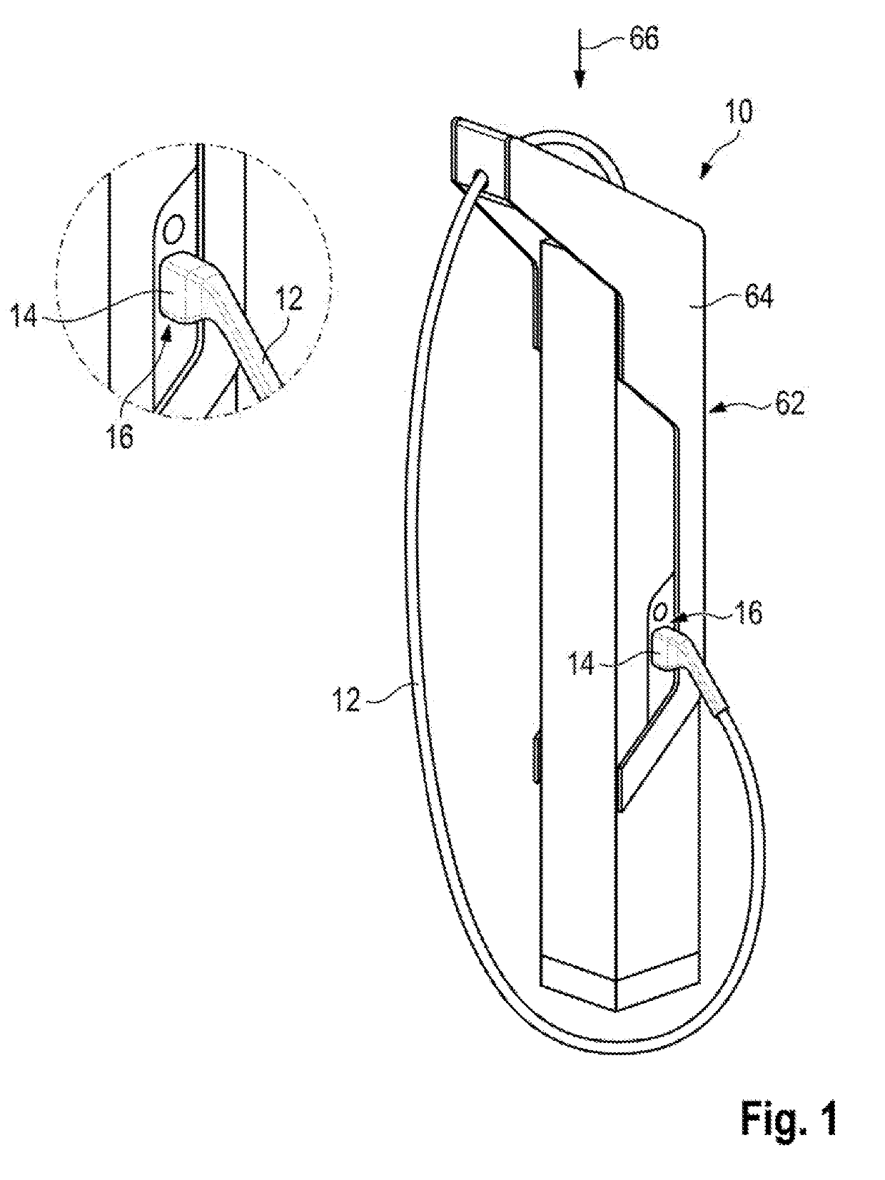
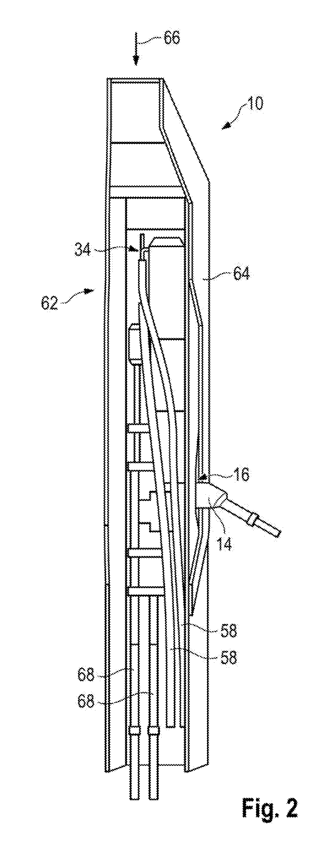
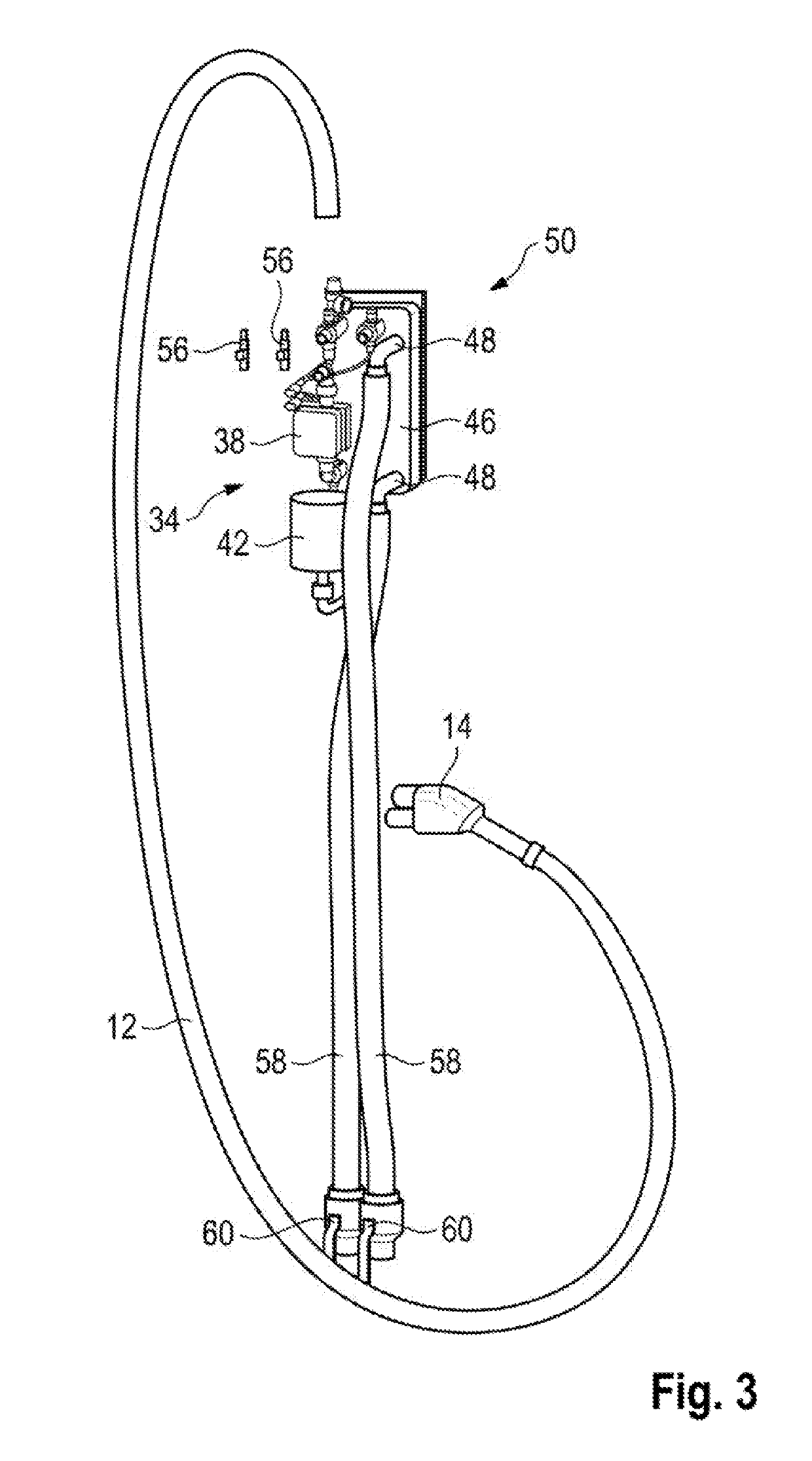
[0054]The charging cable device 50 is illustrated individually in FIG. 3. The charging cable device 50 comprises a temperature control device 34 and a charging cable 12 which is connected thereto. The charging cable 12 is embodied at its end remote from the temperature control device 34 with a charging plug 14 according to the Cable Standard Combined Charging System (CCS) Combo type 2. The charging plug 14 is held, when not in use, in a holder 16 of the fast charging station 10.
[0055]Various charging cables 12 are described below with reference to FIGS. 6 to 8, which charging cables 12 can be used for example in the charging cable device 50.
[0056]A charging cable 12 according to a second embodiment is illustrated in detail in FIG. 6. The charging cable 12 according to the second embodiment comprises two DC charging lines 18 as charging conductors with corresponding insulations 20 which are arranged in ,a charging cable sheath 22. The DC charging lines 18 are embodied here as DC cha...
third embodiment
[0062]The charging cable 12 comprises two DC charging lines 18 with corresponding insulations 20 which are arranged in a charging cable sheath 22. The DC charging lines 18 are, arranged there together with a ground conductor 24 which is surrounded by a corresponding ground insulation 26.
[0063]The charging cable 12 comprises, distributed over the cross section of the charging cable sheath 22, a multiplicity of signal conductors 28 with which the vehicle can communicate with the fast charging station 10.
[0064]Moreover, two fluid lines 30, in which a fluid can circulate, are formed in the charging cable sheath 22. The two fluid lines 30 are arranged concentrically within the charging cable sheath 22 and separated from one another by a separating wall 32. Both the two DC charging lines 18 and the ground conductor 24 are positioned here in a central region of the charging cable 12 within the same fluid line 30.
[0065]Also according to the third embodiment, the two fluid lines 30 are conn...
fourth embodiment
[0067]The charging cable 12 comprises two DC charging lines 18 with corresponding insulations 20 which are arranged in a charging cable sheath 22. The DC charging lines 18 are arranged there together with a ground conductor 24 which is surrounded by a corresponding ground insulation 26.
[0068]The charging cable 12 illustrated in FIG. 8 also comprises a multiplicity of signal conductors 28 with which the vehicle can communicate with the fast charging station 10. However, these signal conductors are not illustrated in FIG. 8, but can be arranged as described with respect to the charging cables 12 according to the second and third embodiment.
[0069]Moreover, two fluid lines 30, in which a fluid can circulate, are constructed within the charging cable sheath 22. The two fluid lines 30 are each constructed concentrically Within the two DC charging lines 18. Also according to the fourth embodiment, the two fluid lines 30 are connected to the temperature control device 34 at an end facing s...
PUM
 Abstract
Description
Claims
Application Information