Wireless sensor networks

Active Publication Date: 2014-08-21
DRAGER SAFETY
View PDF9 Cites 19 Cited by
  • Summary
  • Abstract
  • Description
  • Claims
  • Application Information

AI Technical Summary

Benefits of technology

[0018]As a corollary to this the interrogating node may comprise a sensor for sensing a parameter such that the interrogating node can itself detect and report an alarm condition without having to communicate with a further interrogating node.
[0019]Preferably the sensor unit is ba

Problems solved by technology

However there are some applications where timing is critical to safety.
This can be achieved by using a high update rate but this comes at

Method used


Image

  • Wireless sensor networks
  • Wireless sensor networks
  • Wireless sensor networks

Examples


Example

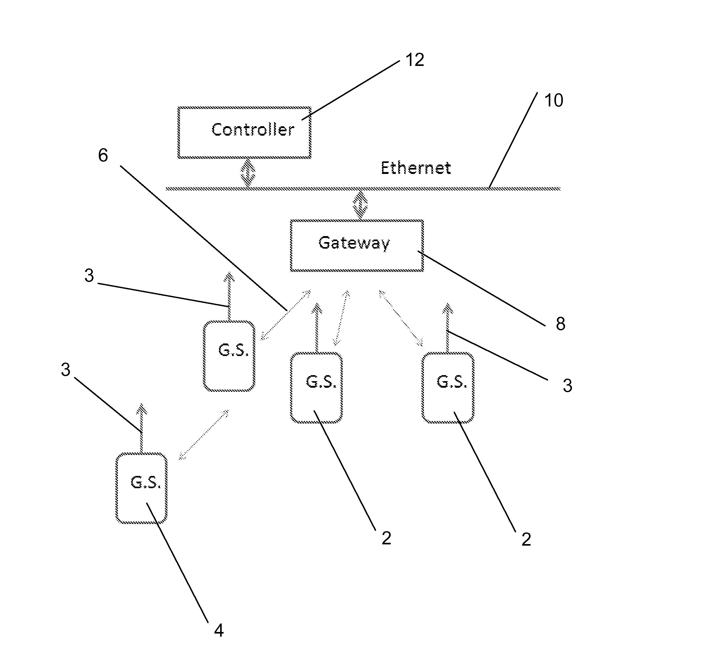
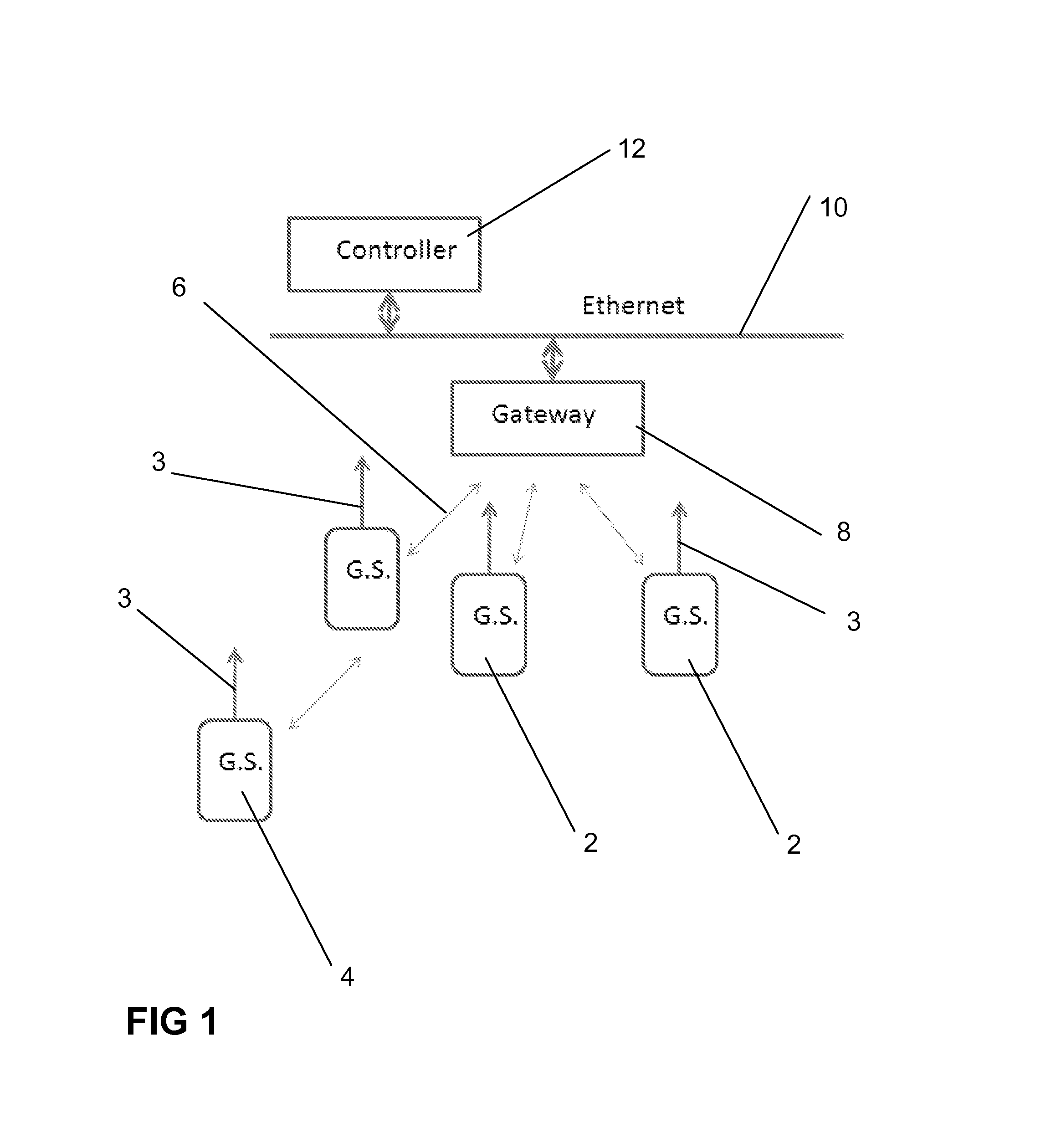
[0030]A preferred embodiment of the invention will now be described, by way of example only, with reference to the accompanying drawings in which:

[0031]FIG. 1 is a schematic representation of a sensor network embodying the invention;

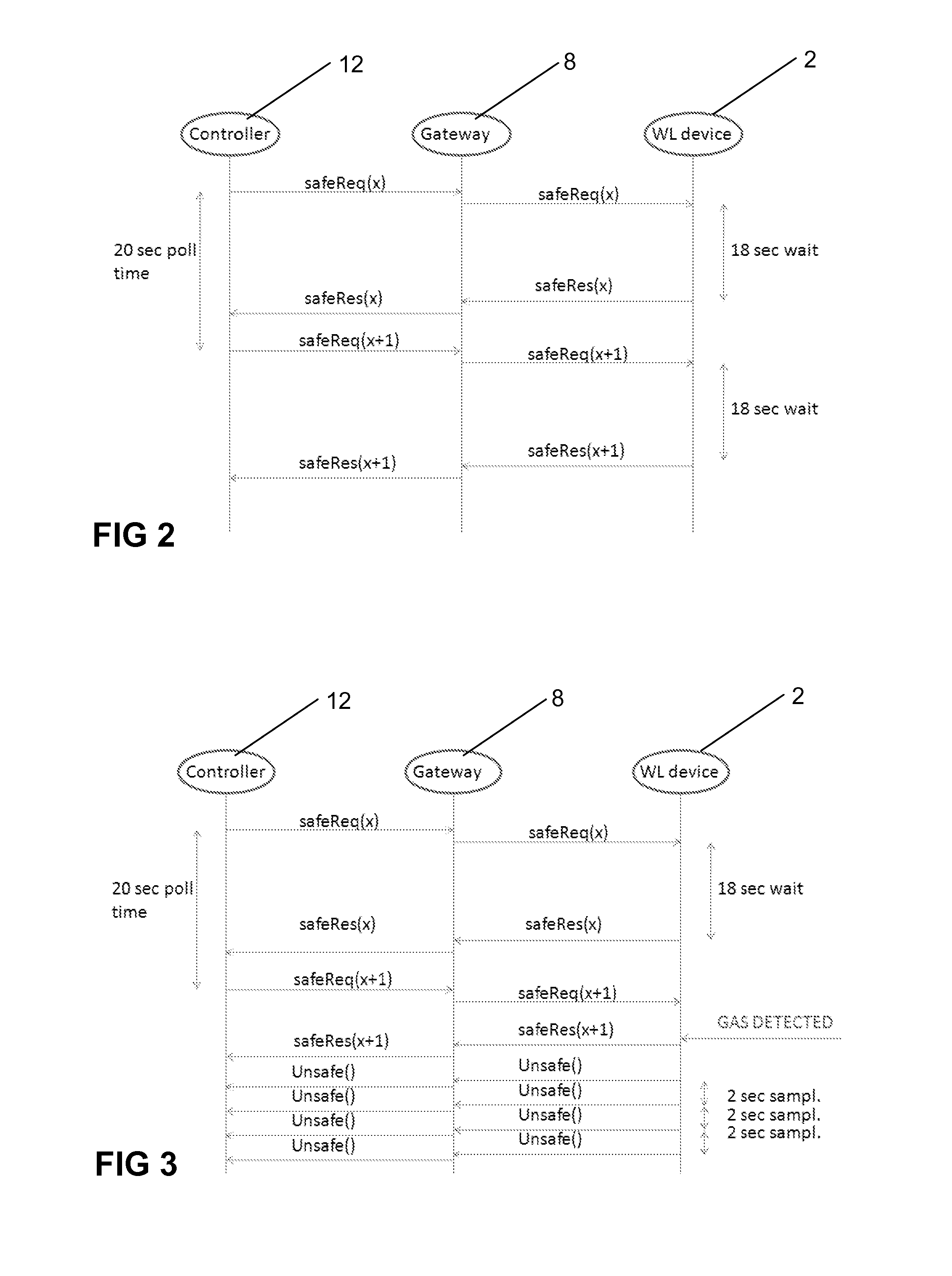
[0032]FIG. 2 is a communication timing diagram relating to normal operation; and

[0033]FIG. 3 is a communication timing diagram relating to an alarm condition operation

DETAILED DESCRIPTION

[0034]Referring first to FIG. 1, there can be seen a network of hydrocarbon gas sensor units 2, 4. Each of the sensor units 2, 4 comprises a gas detector and a 2.4 GHz radio transmitter and receiver which are designed to operate the ISA100.11a or Wireless HART communication protocol, connected to an antenna 3. Of course these particular details are merely illustrative and other sensors and / or communication methods could be used instead.

[0035]Some of the sensor units 2 have a direct two-way radio link 6 with a gateway or proxy 8 which acts as an interrogating node as will...


PUM


Abstract

A wireless sensor network comprises at least one sensor unit which comprises a sensor for sensing a parameter and at least one interrogating node. The interrogating node is arranged to transmit an interrogation message periodically to said sensor unit and to receive a reply message from said sensor unit. The sensor unit is arranged to transmit said reply message after a predetermined deliberate delay unless the sensor unit determines that an alarm condition has been met, in which case the sensor unit is arranged to transmit said reply message before the end of the deliberate delay.

Description

CROSS-REFERENCE TO RELATED APPLICATIONS[0001]This application is a U.S. National Stage entry under 35 U.S.C. §371 based on International Application No. PCT / GB2012 / 051330, filed on Jun. 13, 2012, which was published under PCT Article 21(2) and which claims priority to British Patent Application No. 1110757.0, filed on Jun. 24, 2011.FIELD OF THE INVENTION[0002]This invention relates to networks of distributed wireless remote sensor units, typically battery powered, which report data from different physical locations.BACKGROUND OF THE INVENTION[0003]Such remote sensor networks are well known and used in a variety of different applications—e.g. for reporting temperature, pressure etc. They offer a way of obtaining data from a large number of different places which can then be centrally recorded, analysed and used in control systems.[0004]In many applications the purpose of remote sensor networks is to collect data for medium or long term monitoring and performance analysis and thus rel...

Claims


Application Information

Patent Timeline
IPC IPC(8): H04W52/02H04W4/00H04W4/38H04W4/70
CPCH04W4/005H04W52/0209H04W84/18H04W4/38H04W4/70Y02D30/70
Inventor AAKVAAG, NIELSSANDVEN, KNUT
Owner DRAGER SAFETY
Why Eureka
Try Eureka