Light emitting direction controllable liquid crystal spatial light modulator

A technology of spatial light modulator and outgoing light, which is applied in the direction of instruments, optics, nonlinear optics, etc., and can solve the problems of dark state not dark enough, slow response speed, low contrast, etc.

Inactive Publication Date: 2018-02-09
UNIV OF ELECTRONICS SCI & TECH OF CHINA
View PDF8 Cites 3 Cited by
  • Summary
  • Abstract
  • Description
  • Claims
  • Application Information

AI Technical Summary

Problems solved by technology

[0006] (1). The viewing angle is narrow; when the linearly polarized light of the same intensity is incident at different angles, due to the change of the effective refractive index, it becomes elliptically polarized light. After passing through the second polarizer, the outgoing light intensity with different incident angles is no longer equal. Cause viewing angle problem, its viewing angle is less than 40°
[0007] (2). The response speed is slow; the twisted nematic mode liquid crystal light valve works in a natural fallback mode. Since there is no other external force, its response speed exceeds 40ms
[0008] (3). Low contrast; the twisted nematic liquid crystal light valve uses the optical rotation characteristics of liquid crystal, and the contrast is low, especially the dark state is not dark enough.

Method used


Image

  • Light emitting direction controllable liquid crystal spatial light modulator
  • Light emitting direction controllable liquid crystal spatial light modulator
  • Light emitting direction controllable liquid crystal spatial light modulator

Examples


Embodiment

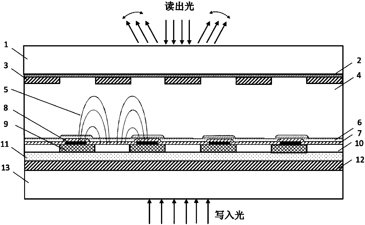
[0031] This embodiment provides a method for preparing a liquid crystal spatial light modulator with a controllable direction of outgoing light, including the following steps:

[0032] Step A: preparing a photosensitive layer 11;

[0033] In this embodiment, two glass substrates are selected as the upper glass substrate 1 and the lower glass substrate 13 respectively, and the second transparent conductive layer 12 is completely deposited on one side of the lower glass substrate 1; A micron-thick, slightly doped amorphous silicon film is used as the photosensitive layer 11. In this embodiment, the material of the photosensitive layer 11 is not limited to a hydrogenated amorphous silicon film. According to common knowledge in the art, the material of the photosensitive layer 11 can be any suitable Material;

[0034] Step B: preparing a reflective layer;

[0035] First, on the photosensitive layer 11 prepared in step A, an electron beam evaporation method is used to deposit a m...


PUM

PropertyMeasurementUnit
electrical resistivityaaaaaaaaaa
relative permittivityaaaaaaaaaa
optical densityaaaaaaaaaa

Abstract

The invention provides a light emitting direction controllable liquid crystal spatial light modulator, and belongs to the technical field of liquid crystal devices. The modulator comprises a first transparent substrate and a second transparent substrate which are relatively arranged in parallel, and a first alignment layer, a first transparent conductive layer, a liquid crystal layer, a second alignment layer, a high-resistance isolation layer, an isolation mesh grid, a reflecting layer, a photosensitive layer and a second transparent conductive layer are arranged on the portions from a firstglass substrate to a second glass substrate in sequence. Accordingly, the first transparent conductive layer, the isolation mesh grid, a second conductive layer and a photosensitive area serve as electrodes, a coplanar horizontal electric field is formed between any two adjacent metal reflecting units and the photosensitive area between the metal reflecting units, a vertical electric field is formed between the first transparent conductive layer and the second transparent conductive layer, and the coplanar horizontal electric field and the vertical electric field together drive liquid crystalmolecules. Accordingly, the emission angle of emitted light can be dynamically adjusted while the device visual angle performance is improved, and meanwhile the photosensitive flexibility and the imaging effect are improved by means of structure improvement.

Description

technical field [0001] The invention belongs to the technical field of liquid crystal devices, and in particular relates to a liquid crystal spatial light modulator with controllable direction of outgoing light. Background technique [0002] A spatial light modulator (Spatial Light Modulator, SLM) means that under active control, it can modulate a certain parameter of the light field through liquid crystal molecules, such as modulating the phase through the refractive index, modulating the polarization state through the rotation of the polarization plane, or realizing The conversion of incoherent to coherent light, so as to write certain information into the light wave, achieve the purpose of light wave modulation. [0003] Spatial light modulators can generally be divided into reflective and transmissive according to the way the readout light is read out; and can be divided into optical addressing (OA-SLM) and electrical addressing (EA-SLM) according to the way of input con...

Claims


Application Information

Patent Timeline
Patent Type & Authority Applications(China)
IPC IPC(8): G02F1/1335G02F1/1337G02F1/1339
CPCG02F1/133553G02F1/1337G02F1/1339G02F1/13398
Inventor 王继岷蒋向东曾一雄高升旭董湘
Owner UNIV OF ELECTRONICS SCI & TECH OF CHINA
Why Eureka
Try Eureka