Discharge device and method for manufacturing same
A discharge device and discharge electrode technology, which is applied in the direction of corona discharge device, electrostatic spray device, spray device, etc., can solve the problems that are difficult to meet at the same time
- Summary
- Abstract
- Description
- Claims
- Application Information
AI Technical Summary
Problems solved by technology
Method used
Image

Examples
no. 1 Embodiment approach
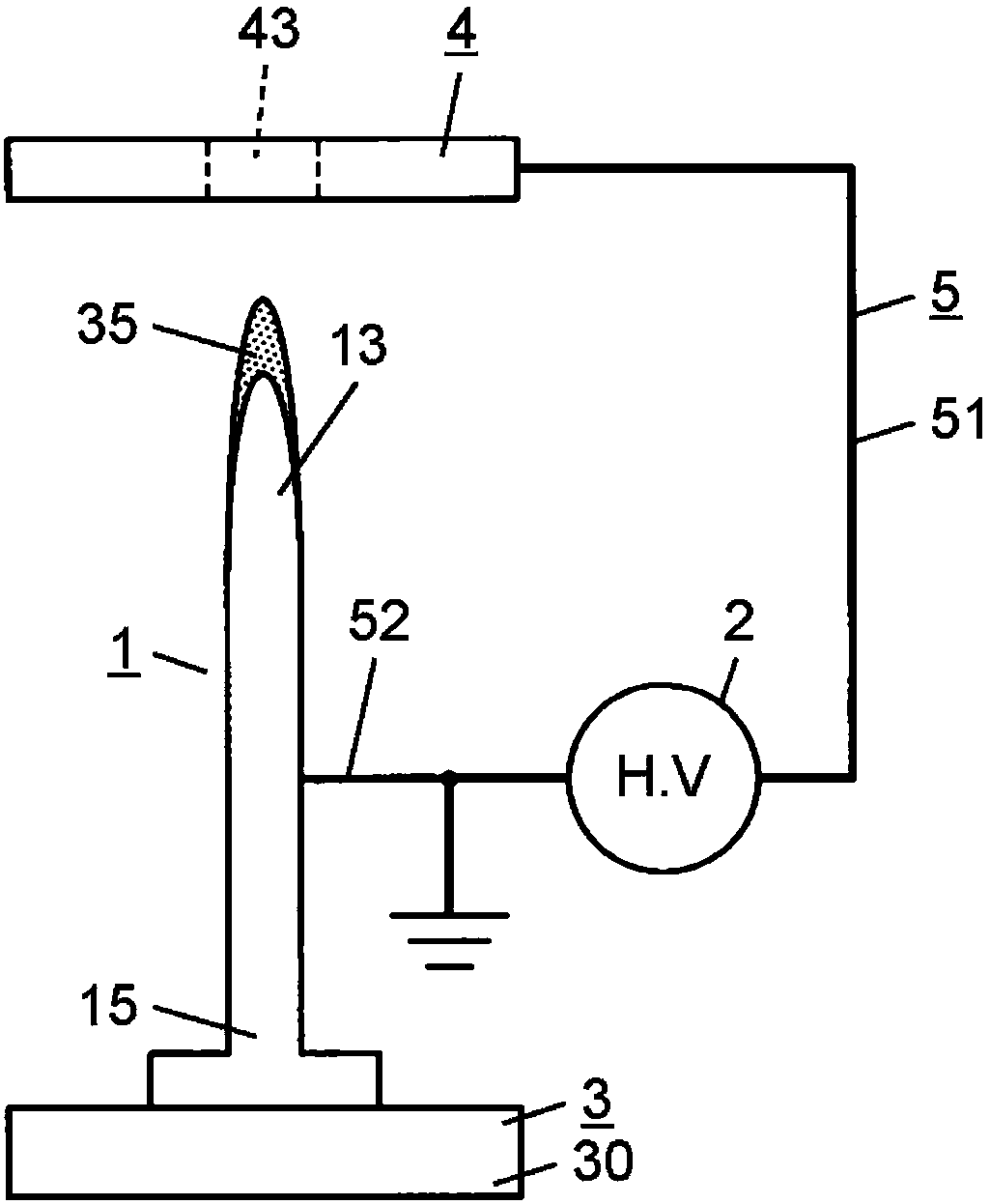
[0064] exist figure 1 The basic configuration of the discharge device of the first embodiment is shown in . The discharge device of this embodiment includes a discharge electrode 1 , a voltage application unit 2 , a liquid supply unit 3 , a counter electrode 4 , and a conduction path 5 .
[0065] The discharge electrode 1 is an elongated needle-shaped electrode. The discharge electrode 1 has a tip portion 13 on one end side in the axial direction thereof, and has a base end portion 15 on the other end side (opposite side to the tip portion 13 ) in the axial direction. The word "needle" used in this application document is not limited to the case where the tip is sharp, but also includes the case where the tip is rounded.
[0066] The voltage application part 2 is electrically connected to the discharge electrode 1 so that the high voltage of about 7.0 kV can be applied to the discharge electrode 1. The discharge device of this embodiment includes a counter electrode 4 , an...
no. 2 Embodiment approach
[0085] based on Figure 3A , Figure 3B The discharge device of the second embodiment will be described. In addition, detailed descriptions of the same configurations as those described in the first embodiment are omitted.
[0086] exist Figure 3A The basic structure of the discharge device of this embodiment is shown in . The discharge device of the present embodiment differs from the first embodiment in that the counter electrode 4 integrally includes the needle-shaped electrode portion 41 and the support electrode portion 42 supporting the needle-shaped electrode portion 41 .
[0087] The needle-shaped electrode part 41 is an electrode part protruding toward the side close to the discharge electrode 1 from the opposing surface 420 which opposes the discharge electrode 1 in the support electrode part 42 . The needle-shaped electrode portion 41 has a sharp convex surface. In the entire counter electrode 4 , the tip of the needle-shaped electrode portion 41 is located cl...
no. 3 Embodiment approach
[0093] based on Figure 4A , Figure 4B A discharge device according to a third embodiment will be described. In addition, detailed descriptions of the same configurations as those described in the first embodiment are omitted.
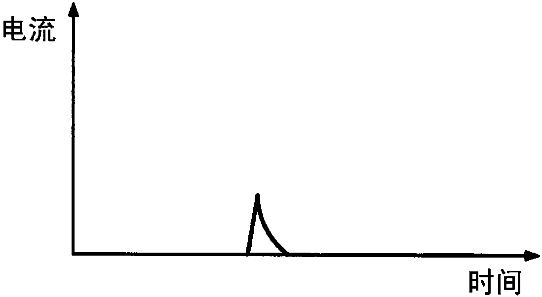
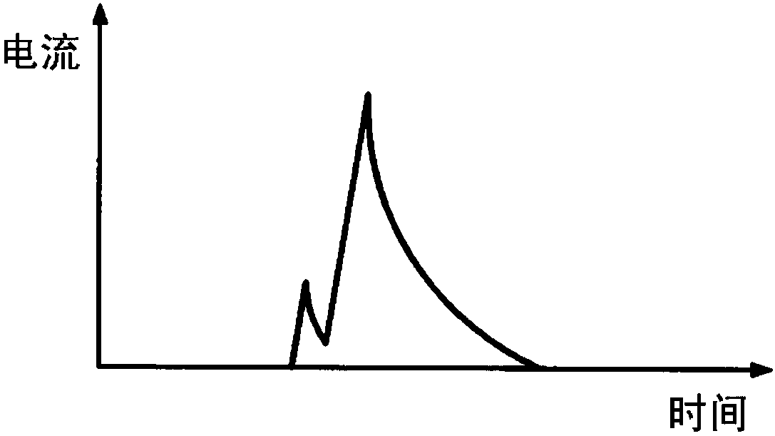
[0094] exist Figure 4A The discharge device of this embodiment is shown in . In the discharge device of the present embodiment, a limiting resistor 6 for adjusting the current peak value of the pilot discharge is provided in the middle of the conduction path 5 electrically connecting the discharge electrode 1 and the counter electrode 4 . Specifically, the limiting resistor 6 is arranged in the middle of the first electric path 51 electrically connecting the voltage application unit 2 and the counter electrode 4 among the electric paths 5 .
[0095] In the pilot discharge, since the instantaneous current flows through the discharge path formed by insulation breakdown, the resistance against the current at this time becomes very small. Therefore, ...
PUM
 Abstract
Description
Claims
Application Information