
Intramedullary needle extending efficiently

An intramedullary needle and high-efficiency technology, applied in the field of efficient extension of the intramedullary needle, can solve the problems that patients are easy to touch the steel needle, the steel needle is pulled out of the body, and affects the treatment effect, so as to reduce the treatment cost, simplify the adjustment, and reduce the scarring of the needle hole. little effect

Inactive Publication Date: 2018-02-16
CHENGDU RONGCHUANG ZHIGU SCI & TECH
View PDF0 Cites 3 Cited by
  • Summary
  • Abstract
  • Description
  • Claims
  • Application Information

AI Technical Summary

Problems solved by technology

[0004] Based on the above technical problems, the present invention provides a high-efficiency extended intramedullary needle, thereby solving the technical problems of inconvenient adjustment in the prior art and the need to lead the steel needle out of the body, causing the patient to easily touch the steel needle and affecting the therapeutic effect.

Method used


Image

  • Intramedullary needle extending efficiently
  • Intramedullary needle extending efficiently

Examples


Embodiment 1

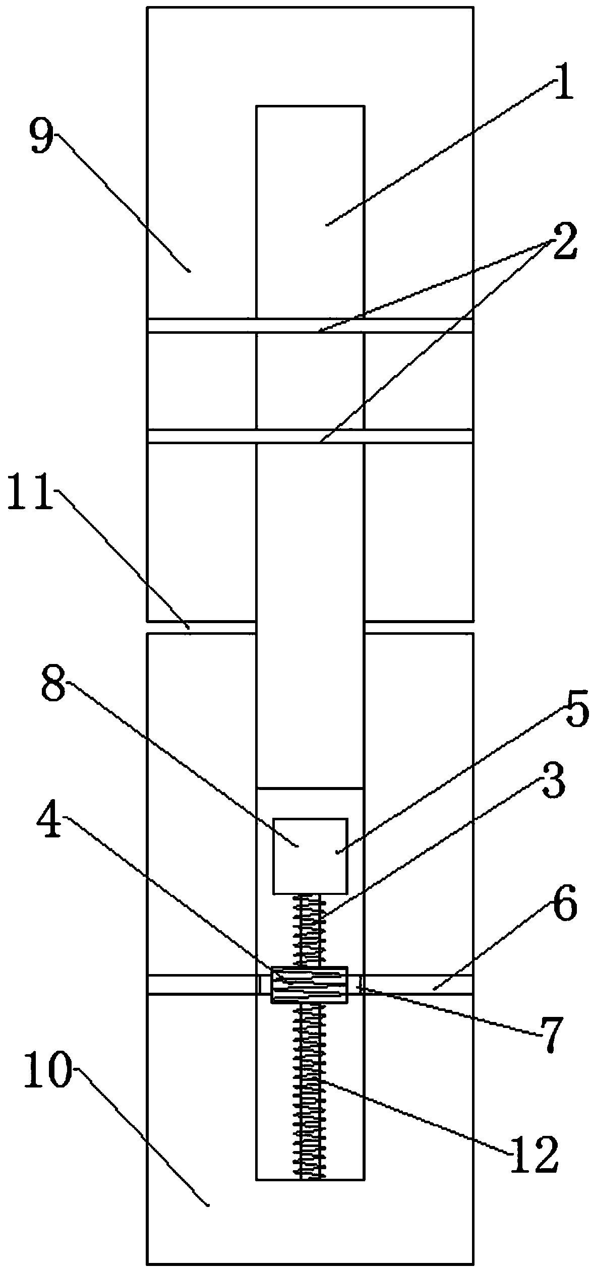
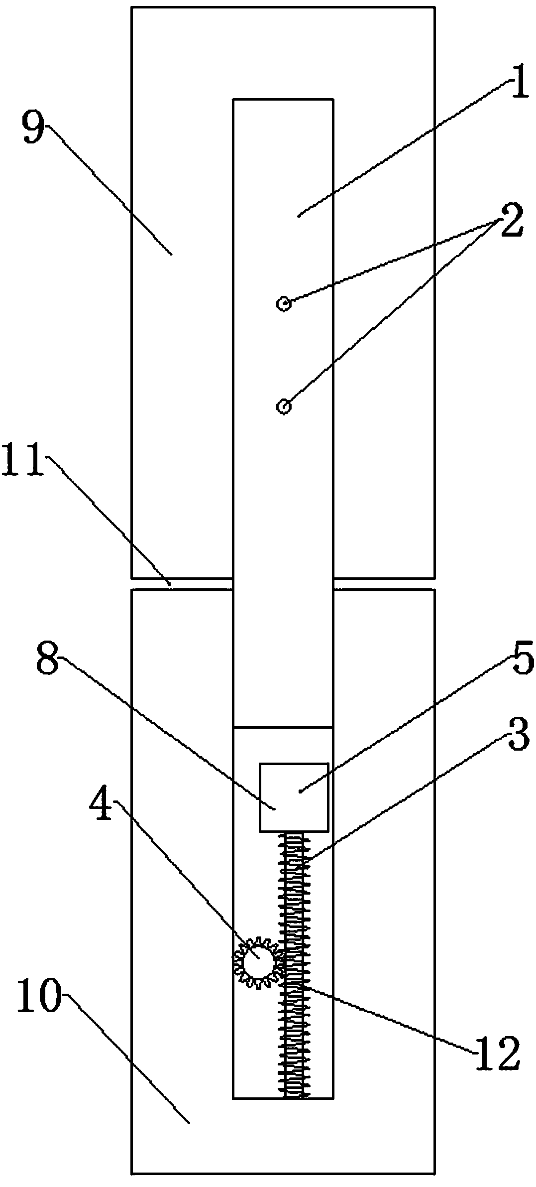
[0027] A high-efficiency extended intramedullary nail, comprising an intramedullary nail main body 1, a fixing nail 2, and an adjustment device 3 arranged inside the intramedullary nail main body 1; set at the lower part of the main body 1 of the intramedullary nail;

[0028] The adjustment device 3 includes an adjustment cylinder 4 arranged horizontally, an anti-rotation drive device 5 is arranged above the adjustment cylinder 4, and the anti-rotation drive device 5 is connected with a vertically downward screw rod 12, and the screw rod 12 is in contact with the outer surface of the adjustment cylinder 4. Engagement, the anti-rotation driving device 5 can drive the adjustment cylinder 4 to move in the vertical direction;

[0029] Both ends of the adjustment cylinder 4 are symmetrically provided with fixed columns 6, and the fixed columns 6 protrude outward from the main body 1 of the intramedullary needle. Bearings 7 are arranged between the adjustment cylinder 4 and the two ...

Embodiment 2

[0031] This embodiment is further optimized based on Embodiment 1. The anti-rotation driving device 5 includes a motor 8 and an electromagnetic brake device arranged inside the motor 8. The electromagnetic brake device can prevent the motor 8 from rotating when it is not working, thereby adjusting The cylinder 4 is fixed to prevent the adjustment cylinder 4 from rotating due to the movement between the bones during use, which will change the gap 11 between the broken bones and affect the treatment effect.

Embodiment 3

[0033] This embodiment is further optimized based on Embodiment 1. There are multiple fixation nails 2, so as to increase the connection strength between the main body of the intramedullary nail 1 and the upper bone 9 .


PUM


Abstract

The invention relates to the technical field of medical devices, and discloses a high-efficiency extended intramedullary nail, which includes a main body of the intramedullary nail, a fixing nail and an adjustment device; The adjustment device includes an adjustment cylinder, an anti-rotation driving device is arranged above the adjustment cylinder, and the anti-rotation drive device can drive the adjustment cylinder to move in the vertical direction; two ends of the adjustment cylinder are symmetrically provided with fixed columns, and the distance between the adjustment cylinder and the two fixed columns is equal. Bearings are provided, and a control system is provided inside the anti-rotation driving device, and the control system is connected to the remote control device for signals; when adjusting, the present invention only needs to use the remote control device to control the adjustment device, thereby controlling the gap between the broken bones , the adjustment is simple and convenient; the present invention does not need to protrude the fixation pin and the fixation post from the outside of the body, thereby requiring fewer pinholes, and can prevent the patient from touching the fixation pin and the fixation post during use, which will affect the therapeutic effect.

Description

technical field [0001] The invention relates to the technical field of medical devices, in particular to a high-efficiency extension intramedullary nail. Background technique [0002] Nowadays, people pay more and more attention to their own health and external image, and they all hope to have a healthy body and an ideal figure. With the development of bone lengthening technology, more and more people who want to increase their height can realize their dreams through bone lengthening. [0003] Limbs are composed of bones, muscles, nerves, blood vessels, skin and other structures. To increase the length of limbs, the length of these structures must be increased. Among them, the role of bones is the most important, and it is difficult to extend them. The commonly used method is to cut off the bone through surgery, and multiple groups of steel needles or steel nails pass through the perforation of the intramedullary nail, and lead out of the body, and are connected to a fixat...

Claims


Application Information

Patent Timeline
Patent Type & Authority Applications(China)
IPC IPC(8): A61B17/72
CPCA61B17/7225
Inventor 章显红
Owner CHENGDU RONGCHUANG ZHIGU SCI & TECH
Learn More