A mill for drying and pulverizing high-humidity and high-viscosity materials and its application method
A grinding and host technology, applied in grain processing, spray evaporation, evaporator accessories, etc., can solve problems such as the problem of high humidity and high viscosity materials hanging on the wall.
- Summary
- Abstract
- Description
- Claims
- Application Information
AI Technical Summary
Problems solved by technology
Method used
Image
Examples
Embodiment 1
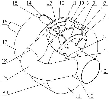
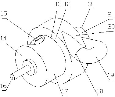
[0048] Embodiment 1: a kind of circulating mill host, see figure 1 and figure 2 , consisting of a housing, a rotor, and an internal circulation pipe 19, the housing is composed of a feed pipe 2, a front cover 1, a cylinder body 20, a middle cover 12, a discharge pipe 17 and a rear cover 14, and the feed pipe 2 The inlet 3 is the inlet of the main engine of the circulating mill, the inlet 4 is on the front cover 1, the internal circulation pipe interface 18 is on the cylinder body 20, the outlet 13 is on the middle cover 12, the circulating mill outlet 15 is on the discharge pipe 17, and the rear cover 14 is on There is a drive shaft hole, a sealing device is arranged on the drive shaft hole of the back cover, the outlet of the feed pipe 2 is connected with the inlet 4 on the front cover 1, the front cover 1 is set at the front end of the cylinder body 20, and the middle cover 12 is set at the The rear end of the body 20, the front end of the discharge pipe 17 is connected to...
Embodiment 2
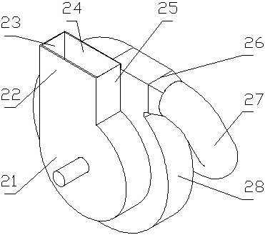
[0049] Embodiment 2: the second kind of circulating mill host, see image 3 , consisting of a housing, a rotor and an internal circulation pipe, the housing is composed of a feed pipe, a front cover, a cylinder body 28, a middle cover, a discharge pipe and a rear cover 21, the inlet of the feed pipe is the inlet of a circulating mill, There is an inlet on the front cover, the cylinder body 28 is a volute, the cylinder body has an internal circulation pipe interface 26, the middle cover has an outlet, and the discharge pipe has a circulation mill outlet, and the circulation mill outlet is a middle plate 24 extending from the middle cover 1. The back cover is composed of the rear plate 22 extending along the stalk, the coaming plate A23 and the coaming plate B25 which are arranged between the middle plate and the rear plate and connect with the opening on the discharge pipe, and the transmission shaft hole is arranged on the back cover, and the feed pipe The outlet is connected ...
Embodiment 3
[0050] Embodiment 3: the third circulating mill main engine, see attached Figure 4 , consisting of a housing, a rotor and an internal circulation pipe 33. The housing is composed of a front cover 35, a cylinder body 30, a middle cover, a discharge pipe and a rear cover. There is an inlet on the front cover, which is the circulation mill main engine. Inlet 36, internal circulation pipe interface 32 and internal circulation pipe outlet interface 34 on the cylinder body 30, outlet on the middle cover, outlet 31 of the main engine of the circulating mill on the discharge pipe, transmission shaft hole on the back cover, and front cover 35 At the front end of the cylinder body 30, the middle cover is arranged at the rear end of the cylinder body 30, the front end of the discharge pipe is connected to the outlet on the middle cover, and the rear cover is arranged at the rear end of the discharge pipe; the rotor is composed of a disc 37, a transmission shaft 39. Composed of grinding ...
PUM
 Abstract
Description
Claims
Application Information
 - R&D
- Intellectual Property
- Life Sciences
- Materials
- Tech Scout
- Unparalleled Data Quality
- Higher Quality Content
- 60% Fewer Hallucinations
Browse by: Latest US Patents, China's latest patents, Technical Efficacy Thesaurus, Application Domain, Technology Topic, Popular Technical Reports.
© 2025 PatSnap. All rights reserved.Legal|Privacy policy|Modern Slavery Act Transparency Statement|Sitemap|About US| Contact US: help@patsnap.com


