Ultrasonic-assisted impressing connecting device and method
An ultrasonic-assisted, connecting device technology, applied in welding equipment, non-electric welding equipment, metal processing equipment, etc., can solve the problems of hard-to-deform materials, easy to generate cracks, difficult deformation, etc., to reduce the probability of gaps, reduce down Compressive resistance, the effect of improving mechanical properties
- Summary
- Abstract
- Description
- Claims
- Application Information
AI Technical Summary
Problems solved by technology
Method used
Image
Examples
Embodiment 1
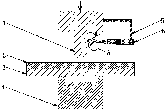
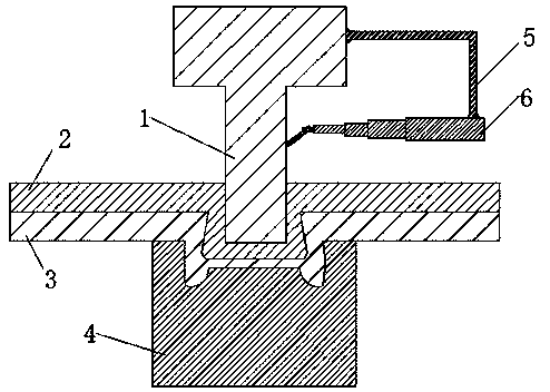
[0030] Embodiment 1: as Figure 1-4 As shown, an ultrasonic-assisted embossing connection device includes a punch 1, a lower riveting die 4, a curved frame 5, a retractable rod 6, and an ultrasonic generator 12; the upper end of the punch 1 is connected to an external imprinting system , one end of the curved frame 5 is welded to the side wall of the punch 1, and the other end is welded to the end of the telescopic rod 6; the top of the telescopic rod 6 is welded with two ribs 13; the ultrasonic generator 12 is installed on the telescopic rod 6 On the two ribs 13 of the top.
[0031] Further, the two ribs 13 are provided with threaded through holes corresponding to each other, and one end of the ultrasonic generating device 12 is hinged to the set screw 14 at the grooved concave end. By adjusting the angle of the ultrasonic generating device 12 and the telescopic rod 6 The length of the punch 1 can make the angle B between the side wall of the punch 1 and the ultrasonic gener...
Embodiment 2
[0045] Embodiment 2: as Figure 1-4 As shown, an ultrasonic-assisted embossing connection device and method, this embodiment is the same as Embodiment 1, wherein:
[0046] Further, the ultrasonic power of the ultrasonic generating device 12 is 1 kW, and the amplitude is 1 μm.
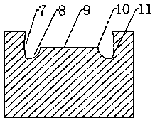
[0047] Further, the radii of the arc side C10 and the arc side D11 are both 2mm.
[0048] Further, the horizontal length of the straight edge 9 is 0.55 of the horizontal length of the bottom of the lower riveting die 4 .
[0049] Further, the radius of the arc edge B8 is 0.35 of that of the straight edge 9 .
[0050] In the step Step2, set the angle B between the ultrasonic generating device 12 and the punch 1 to be 0°;
[0051] In Step 4, the punch 1 moves downward to punch the sheet material, causing plastic deformation of the upper and lower plates, until the concave die of the lower riveting die 4 is fully filled, and the ultrasonic vibration is maintained for 2 seconds.
Embodiment 3
[0052] Embodiment 3: as Figure 1-4 As shown, an ultrasonic-assisted embossing connection device and method, this embodiment is the same as Embodiment 1, wherein:
[0053] Further, the ultrasonic power of the ultrasonic generating device 12 is 100 kW, and the amplitude is 70 μm.
[0054] Further, the radii of the arc side C10 and the arc side D11 are both 3 mm.
[0055] Further, the horizontal length of the straight edge 9 is 0.7 of the horizontal length of the bottom of the lower riveting die 4 .
[0056] Further, the radius of the arc edge B8 is 0.4 of that of the straight edge 9 .
[0057] In the step Step2, set the angle B between the ultrasonic generating device 12 and the punch 1 to be 180°;
[0058] In Step 4, the punch 1 moves downward to punch the sheet material, causing plastic deformation of the upper and lower plates, until the concave die of the lower riveting die 4 is fully filled, and the ultrasonic vibration is maintained for 6 seconds.
PUM
| Property | Measurement | Unit |
|---|---|---|
| radius | aaaaa | aaaaa |
Abstract
Description
Claims
Application Information
 - R&D
- Intellectual Property
- Life Sciences
- Materials
- Tech Scout
- Unparalleled Data Quality
- Higher Quality Content
- 60% Fewer Hallucinations
Browse by: Latest US Patents, China's latest patents, Technical Efficacy Thesaurus, Application Domain, Technology Topic, Popular Technical Reports.
© 2025 PatSnap. All rights reserved.Legal|Privacy policy|Modern Slavery Act Transparency Statement|Sitemap|About US| Contact US: help@patsnap.com


