Battery, battery current collector, and welding method for battery current collector

A current collector and battery technology, applied in welding equipment, resistance welding equipment, battery pack components, etc., can solve the problems of power performance decline, contact internal resistance increase, difficult to operate, etc., to improve power and service life, reduce down Pressure resistance, simple structure effect

Active Publication Date: 2014-02-26
ZHENGZHOU YUTONG BUS CO LTD
View PDF5 Cites 0 Cited by
  • Summary
  • Abstract
  • Description
  • Claims
  • Application Information

AI Technical Summary

Problems solved by technology

Part or all of the power of the electric vehicle is provided by the battery, so the battery used must have certain power characteristics. The tabs on the battery are used as the lead-out ends of the positive and negative electrodes, which are connected to the casing or directly lead out, and are responsible for the current conduction between the outside and the electrodes. Most of the existing tabs use thickened and widened tabs or multi-tab structures, and the material and length of the tabs will seriously affect the battery assembly and battery performance. Thickened and widened tabs The tabs will make it difficult to weld the tabs and the positive and negative carriers or the welding of the tabs and the battery cap, and it is difficult to ensure the consistency of the welding. The length of the tabs is long, and the welding of the tabs will easily cause the battery to fail when assembled. A short circuit occurs during the process, and the capping becomes very difficult and easy to damage the pole group. If the length of the tab is too short, it is easy to make it difficult for the assembly workshop to operate when welding the cap; the multi-tape structure increases the diameter of the battery when the pole group is wound. , the contact area of ​​the positive and negative electrodes is reduced and the welding of multiple tabs and the battery cap is more difficult. It will also damage the pole group, and will increase the contact internal resistance between the positive and negative pole carriers and the battery caps or between the battery shells, and the power performance will decrease, which cannot meet the long-life requirements of the whole vehicle.

Method used


Image

  • Battery, battery current collector, and welding method for battery current collector
  • Battery, battery current collector, and welding method for battery current collector

Examples


Embodiment Construction

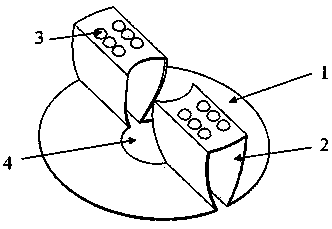
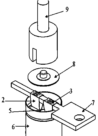
[0020] An embodiment of a current collector of a battery, such as figure 1 As shown, it includes a collecting plate 1 which is integrally bent and formed by a nickel sheet (or copper sheet) and provided with a tab 2. The tab includes two side plates erected on the top surface of the collecting plate. There is a gap for the welding tool to pass through, the bottom of the two side plates is fixed on the collector plate, and the top of the two side plates is bridged and connected with a bridge plate for welding connection with the battery cap and for supporting on the welding tool during welding , the two side plates and the bridging plates together form an inverted U-shaped groove for the welding tool to pass through. The collecting plate 1 is a disc, and the center of the collecting plate 1 is provided with a hole 4 for liquid injection or welding. The ear 2 is arranged symmetrically around the center of the current collecting plate, the bridging plate of the tab 2 is provided ...


PUM


Abstract

The present invention discloses a battery, a battery current collector, and a welding method for the battery current collector. The battery current collector comprises a current collection disk prepared by a nickel sheet or a copper sheet. Electrode lugs are convexly arranged on the current collection disk. The electrode lugs comprise two side plates, wherein the two side plates are vertically arranged on the top surface of the current collection disk. A gap is arranged between the two side plates, wherein the gap is provided for the welding tool passing. The bottoms of the two side plates are fixed on the current collection disk. The tops of the two side plates form bridges with bridge plates, wherein the bridge plate forms a welding connection with the battery cover cap, and is supported on the welding tool during the welding process. The two side plates and the bridge plates are enclosed to form an inverted U-shaped groove, wherein the groove is provided for the welding tool passing. The top surfaces of the bridge plates of the electrode lugs are provided with convex points, wherein the convex points are provided for welding with the battery cover cap. The battery current collector of the present invention has a simple structure. With the battery current collector of the present invention, the pushing resistance of the battery cover cap during the electrode lug welding process is effectively reduced, such that no damage is generated to the electrode group during the cover pressing process; the length of the electrode lug of the present invention is short, the ohmic internal resistance between the electrode lug and the battery cover cap is small, such that the power and the service life of the battery are increased.

Description

technical field [0001] The invention relates to the field of batteries, which is a battery current collecting structure, especially a cylindrical battery with high power input and output requirements. At the same time, the invention also relates to a battery using the current collector, and the invention also relates to the current collector and the battery cap. welding method. Background technique [0002] Along with the concept of energy conservation, emission reduction and low carbon are deeply rooted in the hearts of the people, new energy vehicles, especially electric vehicles, have developed rapidly. Part or all of the power of the electric vehicle is provided by the battery, so the battery is required to have certain power characteristics. The tabs on the battery are used as the lead-out ends of the positive and negative electrodes, which are connected to the housing or directly lead out, and are responsible for the current conduction between the outside and the elect...

Claims


Application Information

Patent Timeline
Patent Type & Authority Patents(China)
IPC IPC(8): H01M4/70H01M2/26B23K11/00B23K11/36
CPCY02E60/12Y02E60/10
Inventor 董伟超周时国路丹花杜颖颖
Owner ZHENGZHOU YUTONG BUS CO LTD
Why Eureka
Try Eureka