Cooling liquid recovering structure for blow-molding of chemical experimental containers

A blow molding and chemical experiment technology, applied in the field of plastic products, can solve problems affecting product flatness, difficult to control product quality, plastic film deformation, etc.

Inactive Publication Date: 2018-02-16
成都市森德教学设备有限公司
View PDF0 Cites 4 Cited by
  • Summary
  • Abstract
  • Description
  • Claims
  • Application Information

AI Technical Summary

Problems solved by technology

[0002] Generally, when manufacturing plastic containers for laboratories, blow molding machines are usually used, but a large amount of cooling water is required during use, and the existing blow molding machines do not have a cooling water circulation device designed for use.
A large amount of water is consumed in use, and water resources are not well utilized
And in the process of use, due to the characteristics of the plastic film products produced by the blow molding machine, the cooling water needs to have a certain temperature. Supercooled or superheated water can deform the plastic film, thereby affecting the flatness of the product, and the product quality is difficult to control.
However, the existing equipment does not have such a circulation device, which cannot meet the existing production needs

Method used


Image

  • Cooling liquid recovering structure for blow-molding of chemical experimental containers

Examples


Embodiment 1

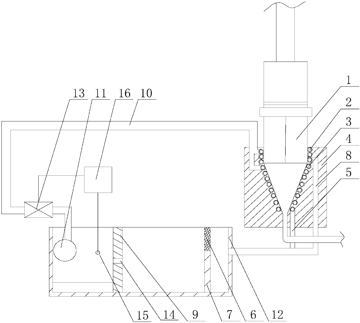
[0020] Such as figure 1 As shown, this embodiment includes a pool body 12 and a water pump 11 fixed on the side wall of the pool body 12. A baffle 7 is arranged at the bottom of the pool body 12, and the baffle plate 7 separates the pool body 12 into mutually independent The sedimentation chamber and the liquid storage chamber, the water pump 11 is placed in the liquid storage chamber, and the horizontal height of the baffle plate 7 is smaller than the depth of the pool body 12, and also includes a heat insulation block 4 sleeved on the outer wall of the discharge section 1 of the blow molding machine, A first branch pipe 2 and a second branch pipe 3 are provided inside the heat insulating block 4, and the first branch pipe 2 is spirally wound at the beginning of the discharge section 1 of the blow molding machine, and the second branch pipe 3 is spirally wound on the blow molding machine. The end of the discharge section 1 of the plastic machine is connected with a liquid out...

Embodiment 2

[0024] Such as figure 1 As shown, in this embodiment, an electric heating plate is provided at the bottom of the liquid storage chamber, and the electric heating plate is located between the liquid storage chamber and the side wall of the separator 9 away from the precipitation chamber, and the electric heating plate passes through The wire is electrically connected with the PLC control box 16 . When the temperature value detected by the temperature sensor 15 is less than the temperature value required by the discharge section 1 of the blow molding machine, the PLC control box 16 starts the electric heating plate while controlling the solenoid valve 13 to be closed, so that the electric heating plate is positioned at its positive position. The cooling liquid above is heated until the detection value of the temperature sensor 15 is slightly higher than the temperature value required by the discharge section 1 of the blow molding machine. The PLC control box 16 controls the elec...


PUM


Abstract

The invention discloses a cooling liquid recovery structure for blow molding of chemical experiment containers, including a pool body and a water pump, a baffle plate is arranged at the bottom of the pool body, a first branch pipe and a second branch pipe are arranged in the heat insulation block, the first The branch pipe is spirally wound at the beginning of the discharge section of the blow molding machine, and the second branch pipe is spirally wound at the end of the discharge section of the blow molding machine. A liquid outlet pipe is connected to the outlet end of the water pump, and the liquid outlet pipe is connected to the inlet of the first branch pipe. end connection, on the outer wall of the pool body, a liquid inlet pipe communicating with the sedimentation chamber is provided, the inlet end of the liquid inlet pipe communicates with the outlet end of the second branch pipe, and a solenoid valve is provided on the liquid outlet pipe; A baffle is arranged in the middle of the liquid storage chamber, and a through hole is opened in the upper part of the baffle, the temperature sensor is electrically connected with the PLC control box, and the PLC control box is electrically connected with the electromagnetic valve. In the technical solution, the cooling water used for the first time is recovered and subjected to a series of treatments, and then used in the cooling process again, thereby achieving the purpose of reducing production costs.

Description

technical field [0001] The invention relates to the field of plastic products, in particular to a cooling liquid recovery structure used for blow molding of chemical experiment containers. Background technique [0002] Generally, a blow molding machine is used to manufacture plastic containers for laboratory use, but a large amount of cooling water is required during use, and the existing blow molding machines do not have a cooling water circulation device designed for use. A large amount of water is consumed in use, and water resources are not well utilized. And in the process of use, due to the characteristics of the plastic film products produced by the blow molding machine, the cooling water needs to have a certain temperature. Supercooled or superheated water can deform the plastic film, thereby affecting the flatness of the product, and the product quality is difficult to control. . However, the existing equipment does not have such a circulation device, which cannot...

Claims


Application Information

Patent Timeline
Patent Type & Authority Applications(China)
IPC IPC(8): B29C49/64B29C49/78
CPCB29C49/64B29C49/786B29L2031/712
Inventor 谢德贤谢静陈跃张红亮
Owner 成都市森德教学设备有限公司
Why Eureka
Try Eureka