Power cycle output method and system for absorbing heat energy from air

A technology for absorbing heat energy and power cycle, applied in the direction of generating mechanical power, machine/engine, steam engine device, etc., can solve the problem of restricting large-scale popularization and use, and achieve easy popularization and implementation, wide application range, and low cost of use. Effect

Inactive Publication Date: 2017-01-04
符海龙
View PDF0 Cites 3 Cited by
  • Summary
  • Abstract
  • Description
  • Claims
  • Application Information

AI Technical Summary

Problems solved by technology

Clean energy represented by solar energy, wind energy, water energy, etc. meet the needs of human beings, but these types of energy have various shortcomings in actual use, which limits their large-scale promotion and use in society

Method used


Image

  • Power cycle output method and system for absorbing heat energy from air
  • Power cycle output method and system for absorbing heat energy from air
  • Power cycle output method and system for absorbing heat energy from air

Examples


Embodiment 1

[0036] Embodiment one: see figure 1 — Figure 6 , the composition and functions of the main equipment in the figure:

[0037] ①A gas-saturated gas storage device

[0038] Function: Store the saturated gas of the working medium A used when the power machine is working.

[0039] ②Condensation nucleus generating device

[0040] Function: produce condensation nuclei that promote the adiabatic expansion of A gas-saturated gas to condense A-saturated liquid.

[0041] The condensation nuclei generated in the device and added to the A saturated gas may be ions, high-energy rays, or other substances.

[0042] ③Positive power output device

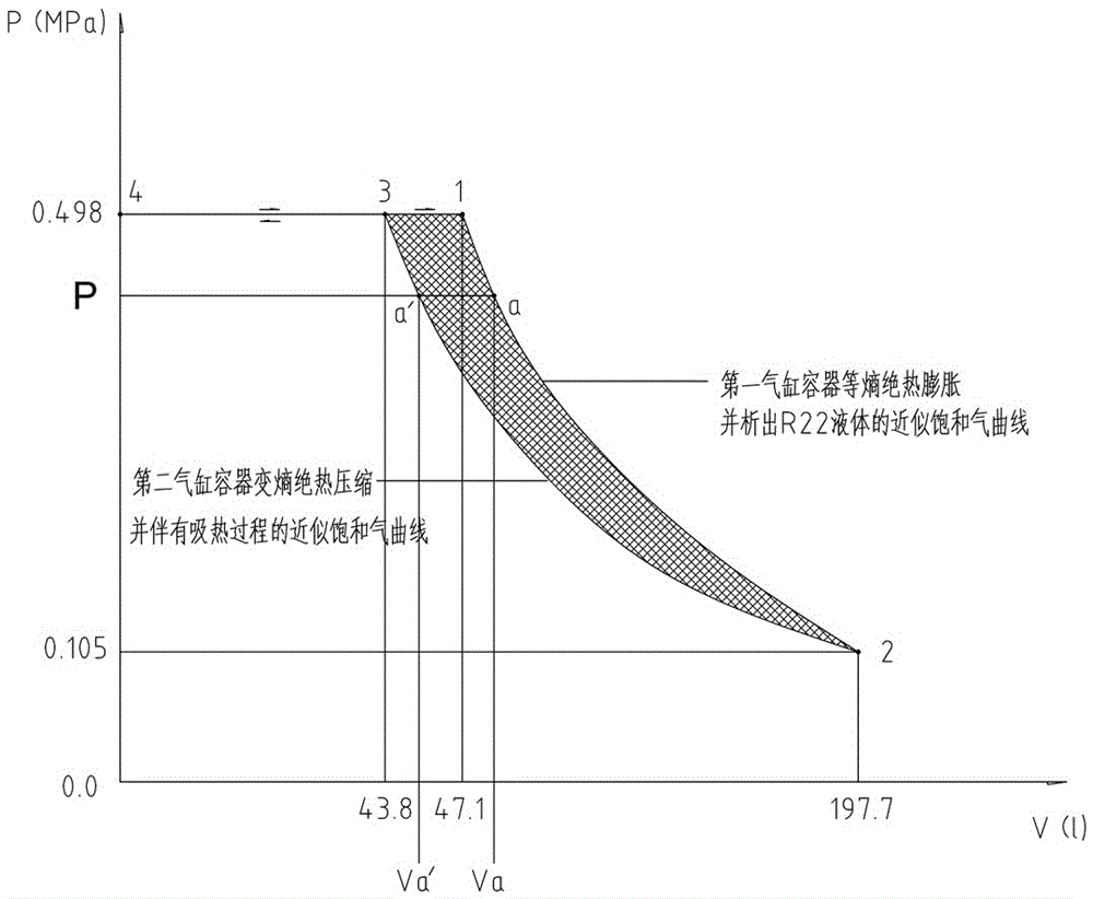
[0043] Function: Similar to the pistons and cylinders used in ordinary engines, A-gas-saturated gas will expand adiabatically in this device and condense A-saturated liquid.

[0044] ④ A gas A liquid separation device

[0045] Function: Completely separate A saturated gas and A saturated liquid that adiabatically expand and condense out of li...

Embodiment 2

[0091] Embodiment two: see Figure 7 , this embodiment is basically the same as Embodiment 1, and the similarities will not be repeated. The difference is that: the low-temperature A saturated liquid and the low-temperature A saturated gas entering the A-gas-A-liquid separation device are fully separated into separate low-temperature A Saturated liquid and low temperature A saturated gas. Then it is divided into two paths, one path is the separated low temperature A saturated liquid, it enters the high pressure pump of liquid A, and enters the heat exchange device of liquid A after pressurization, at this time, the pressure of the low temperature saturated liquid A and the gas saturated gas storage device The pressure of the saturated gas in A is exactly the same, but the temperature is not as high as that of the saturated gas in A. All the way, the separated low-temperature A saturated gas enters the variable capacity compression device through the valve D3, and the valve D3...


PUM


Abstract

The invention discloses a power cycle output method and system for absorbing heat energy from air. An A gas saturation and storage device, a condensation nucleus generation device, a positive work output device, a gas-liquid separation device, an A liquid heat exchange device, an air heat exchange device, an A gas and B liquid mixing device, a negative work input device and an A gas and B liquid separation device are respectively arranged, so that three cycles are performed in normal operation and include an A saturated gas cycle, an A liquid cycle and a B liquid cycle respectively, and the working process is a three-cycle working process. By a heat exchange mode, the air can be cooled, the heat energy of air molecules is absorbed, inexhaustible air internal energy is directly used as an energy source, and the sun ceaselessly supplements the air internal energy every day, the possibility of exhaustion of energy sources is avoided, so that the requirement of humans for unrestricted use of clean energy is met while environmental protection requirements are met.

Description

[0001] Technical field: [0002] The invention relates to a method and system for utilizing air heat energy, in particular to a power cycle output method and system for absorbing heat energy from air. [0003] Background technique: [0004] The known energy sources currently used by human beings include clean energy represented by solar energy, wind energy, water energy, etc. [0005] Fossil energy represented by coal, oil, natural gas, etc., and emerging energy represented by nuclear fission energy and nuclear fusion energy. In addition to clean energy, when humans use other energy sources, they will inevitably damage or pollute the environment, which will have a negative impact on social development. Moreover, the resources of fossil energy and nuclear fission energy are limited and cannot be used by humans without restriction. Nuclear fusion energy is relatively inexhaustible, but the current technology is still immature, and there is still a long way to go before human bei...

Claims


Application Information

Patent Timeline
Patent Type & Authority Applications(China)
IPC IPC(8): F03G7/04F01K25/06F01K25/08
CPCF03G7/04F01K25/06F01K25/08
Inventor 符海龙
Owner 符海龙
Why Eureka
Try Eureka