
Roof-contacted filling monitoring system

A monitoring system and monitoring sensor technology, applied in fillings, mining equipment, earthwork drilling, etc., can solve the problems of inconvenient installation and use, and achieve the effect of easy installation and use

Pending Publication Date: 2018-02-16
CHINA MINMETALS CHANGSHA MINING RES INST
View PDF6 Cites 4 Cited by
  • Summary
  • Abstract
  • Description
  • Claims
  • Application Information

AI Technical Summary

Problems solved by technology

The highly accurate indicator needs to be connected with the controller and the alarm device with a wire, which is not easy to install and use, and is not suitable for goaf filling with large differences in the height of the top of the stope

Method used


Image

  • Roof-contacted filling monitoring system
  • Roof-contacted filling monitoring system
  • Roof-contacted filling monitoring system

Examples


Embodiment 1

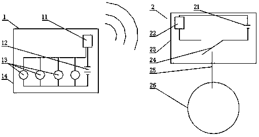
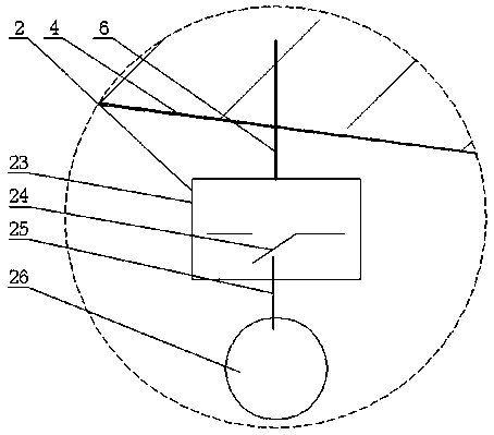
[0024] refer to Figure 1~3 , a filling and topping monitoring system of this embodiment, comprising four topping detection sensors 1 and a topping monitoring display host 2, said topping monitoring sensors including a float 26, a pressure touch switch 24 and a wireless signal transmitter 22. The floating ball 26 is connected to the pressure touch switch 24 through the actuator rod 25, and the wireless signal transmitter 22 is electrically connected to the power supply 12 through the pressure touch switch 24; device 11 and several light-emitting diodes 13, the light-emitting diodes 13 are connected in parallel, and connected to the main power supply 21 through the wireless signal receiver 11, the wireless signal receiver 11 receives the signal sent by the top detection sensor 1, and controls the corresponding The working state of the light emitting diode 13.

[0025] The roof contact monitoring sensor is fixed on the roof 4 of the filling roadway through expansion bolts 6 or ...

Embodiment 2

[0031] refer to Figure 4 , a filling and top-connecting monitoring system of this embodiment, compared with Embodiment 1, there are the following differences:

[0032] A filling top contact monitoring system includes six top contact detection sensors 1 and a top contact monitoring display host 2 .

[0033] The roof connection detection display host also includes an alarm device, and the alarm device includes several alarm devices 15 corresponding to the roof connection detection sensor 1 .

[0034] The roof contact monitoring sensor is fixed on the roof 4 of the filling roadway by adhesive.

[0035] The working principle and usage method of a filling and roofing monitoring system of the present invention are as follows:

[0036] The top connection monitoring sensor is installed on the top plate 4 of the filling roadway. When filling and top connection, the floating ball 26 will float up and trigger the pressure touch switch 24, and then send a signal to the top connection d...


PUM

PropertyMeasurementUnit
Diameteraaaaaaaaaa

Abstract

A roof-contacted filling monitoring system comprises at least two roof-contacted detecting sensors and a roof-contacted monitoring displaying host. Each roof-contacted detecting sensor comprises a floating ball, a pressure touch control switch and a wireless signal transmitter, the floating balls are connected with the pressure touch control switches through executing rods, and the wireless signaltransmitters are electrically connected with power sources through the pressure touch control switches. The roof-contacted monitoring displaying host comprises a wireless signal receiver and a plurality of light emitting diodes which are connected in parallel and connected with a main power source through the wireless signal receiver. The wireless signal receiver receives signals transmitted by the roof-contacted detecting sensors and controls the work states of the corresponding light emitting diodes. According to the roof-contacted filling monitoring system, the multiple roof-contacted detecting sensors mounted in different vertical heights are adopted, so that the state of roof-contacted filling is conveniently known in time, the construction schemes such as the components of filling slurry and the filling speed are adjusted, filling material waste is few, and stope pollution is low; and the roof-contacted filling monitoring system is suitable for monitoring the filling process ofa goaf with a large top height difference, and mounting and using are facilitated.

Description

technical field [0001] The invention relates to the field of mine stope filling, in particular to a filling roof connection monitoring system. Background technique [0002] The approach filling mining method can effectively solve the high ground pressure mining conditions faced by deep shaft mining, and its mining effect of low dilution loss rate has become one of the widely used mining methods at present. However, the approach-filling mining method has higher requirements on the filling stope roof connection rate. Only a good roof connection can make the filling body play the role of supporting the roof, ensure the safety of the surrounding stope mining, and reduce the effect of dilution loss rate. . However, in the current technology, the jacking operation is all based on manual experience, the quality of the operation varies, and there are problems such as stope pollution and waste of filling materials. [0003] CN 103541764 A discloses an accurate height indicator for ...

Claims


Application Information

Patent Timeline
IPC IPC(8): E21F17/18E21F15/00
CPCE21F15/00E21F17/18
Inventor 郑伯坤黄腾龙李向东
Owner CHINA MINMETALS CHANGSHA MINING RES INST
Learn More