Electric-hydraulic proportional plunger pump

A technology of electro-hydraulic proportional and plunger pumps, applied in variable capacity pump components, liquid variable capacity machines, pumps, etc., can solve the problems of easy vibration, energy waste, easy damage, etc., and increase the axial bearing capacity , the effect of high control precision

A technology of electro-hydraulic proportional and plunger pumps, applied in variable capacity pump components, liquid variable capacity machines, pumps, etc., can solve the problems of easy vibration, energy waste, easy damage, etc., and increase the axial bearing capacity , the effect of high control precision

CN107701385AInactive Publication Date: 2018-02-16广州华欣液压科技股份有限公司

Image

  • Electric-hydraulic proportional plunger pump
  • Electric-hydraulic proportional plunger pump
  • Electric-hydraulic proportional plunger pump

Examples


Embodiment

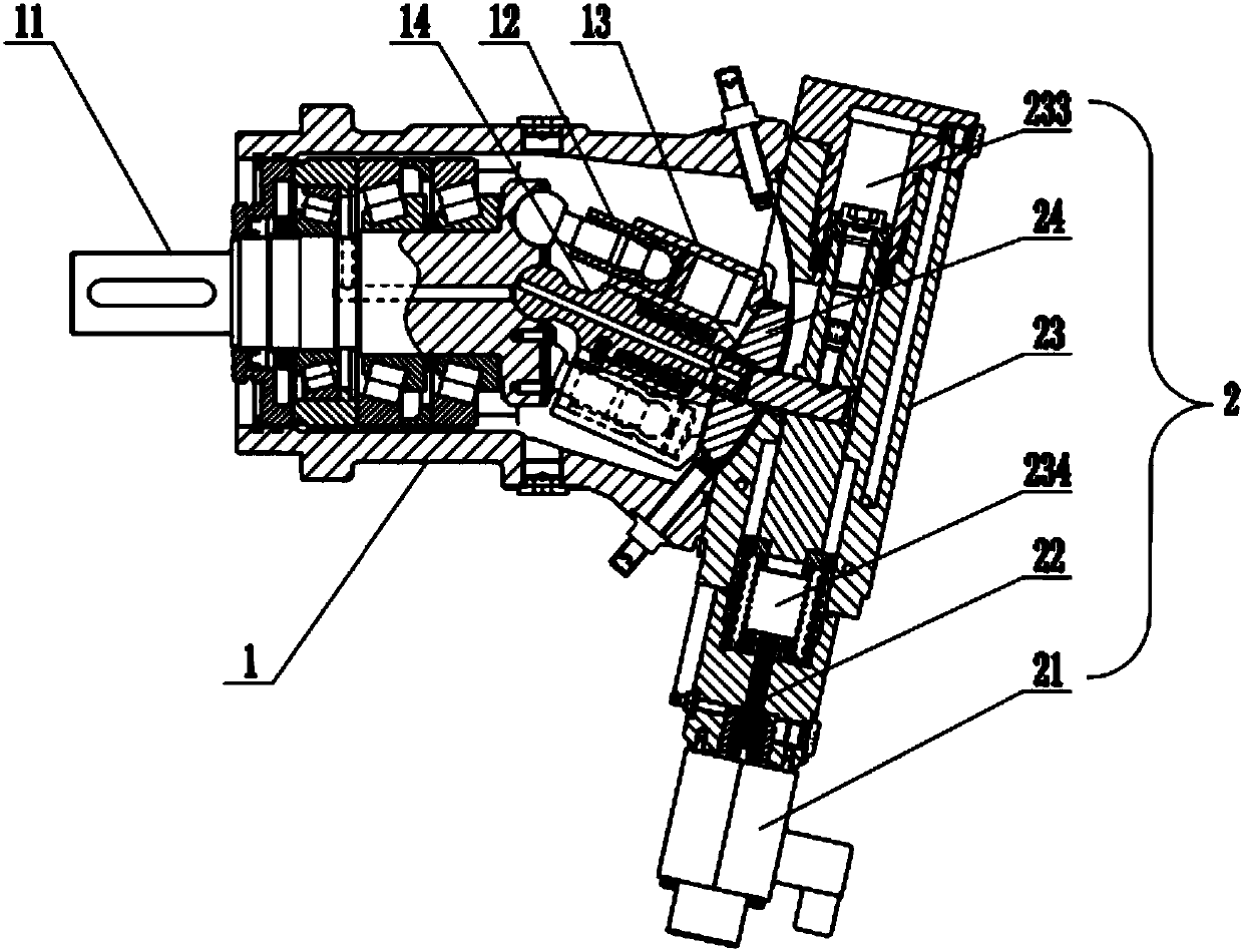
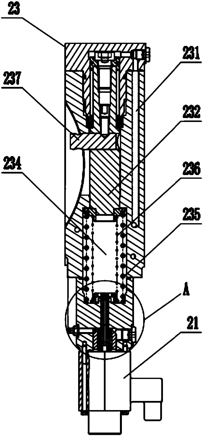
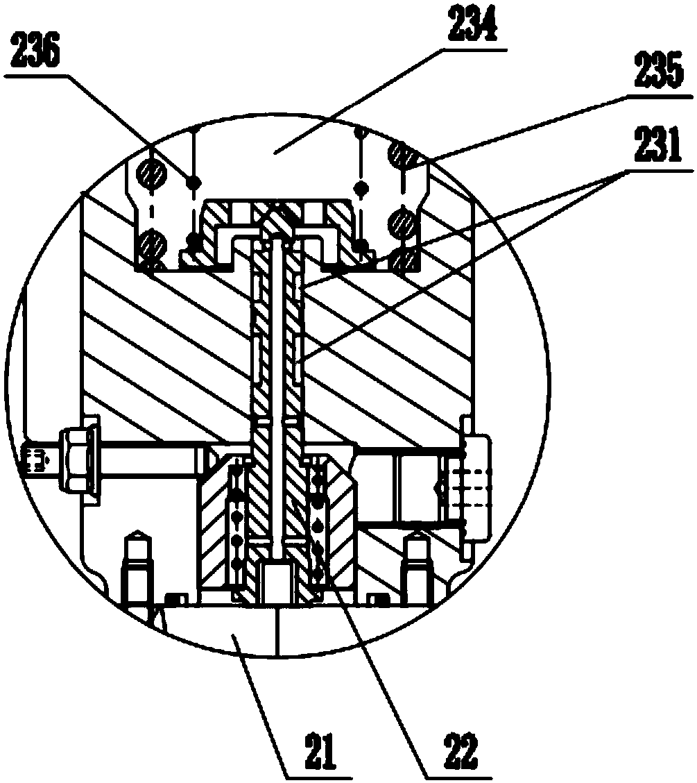
[0036] The specific embodiment of the present invention is as Figure 1 to Figure 6 As shown, an electro-hydraulic proportional plunger pump includes a plunger pump main body 1 and a control device 2 for adjusting the displacement of the pump. Wherein, the plunger pump main body 1 includes a bearing 11 and a central rod 14 for connecting the bearing 11 and the control device 2 and the axis forms an angle with the axis of the bearing 11. There are multiple ends connected to the bearing 11 around the central rod 14. The other end of the plunger 12 is provided with a plunger sleeve 124 and a cylinder body 13 matching the outer diameter of the plunger sleeve 124 in turn. This included angle causes the plunger 12 to rotate once around the center rod 14 When there is a stroke in the cylinder body 13, the oil discharge and oil suction are realized by the back and forth of the stroke, and the adjustment of the included angle has just adjusted the displacement of the pump; the control ...


PUM


Abstract

The invention discloses an electric-hydraulic proportional plunger pump, which belongs to the technical field of plunger pumps, and comprises a plunger pump body and a control device for adjusting pump displacement. The plunger pump body comprises a bearing and a central rod used for connecting the bearing and the control device and provided with an axial line forming an included angle with an axial line of the bearing; a plurality of plungers connected with the bearing are arranged around the central rod; the control device comprises an electromagnet, a displacement and feedback force systemand a control valve element for connecting the electromagnet and the displacement and feedback force system; and an oil distribution disc for installing the central rod is arranged on the displacementand feedback force system. The invention provides the plunger pump which has the displacement capable of being adjusted from zero to maximum infinitude, and is convenient to adjust, higher in rotaryspeed and stain resistant.

Description

technical field [0001] The invention relates to the technical field of plunger pumps, in particular to an electro-hydraulic proportional plunger pump. Background technique [0002] The domestic type similar plunger pumps currently on the market, the structure of the control device (such as Figure 7 As shown) is relatively complicated, the electromagnet 7' is energized to generate thrust, and a very long push rod 4' is used to push the valve core 3', thereby controlling the displacement of the piston 1' and driving the shift fork 2'; at the same time, it is necessary to adjust Adjust the length of the rod 6' to adapt to the distance of the push rod 4'. In addition to the balance of the feedback spring 5', the thrust of the electromagnet 7' must also overcome the gravity of several parts such as the push rod 4', which is prone to vibration during use (electromagnetic The maximum thrust of iron 7' ​​is 80N), which causes variable instability, and the feedback spring 5' for det...

Claims


Application Information

Patent Timeline
16 Feb 2018
Publication
CN107701385A
IPC
F04B1/16; F04B1/29; F04B53/14
CPC
F04B1/16; F04B1/124; F04B1/295
Inventors
余倡合; 虞伟