Oil channel structure of compressor and compressor
A compressor and oil circuit technology, applied in the field of compressors, can solve problems such as the inability to discharge heat in time, achieve good lubrication and cooling effects, improve energy efficiency, and ensure normal operation
- Summary
- Abstract
- Description
- Claims
- Application Information
AI Technical Summary
Problems solved by technology
Method used
Image

Examples
Embodiment 2
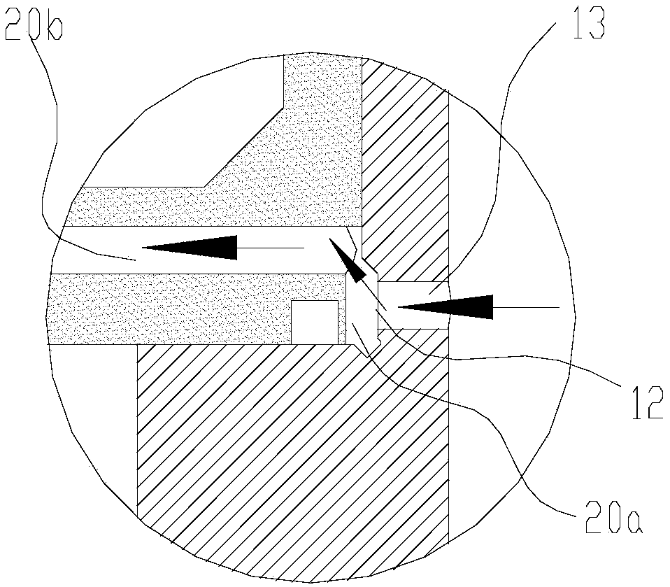
[0074] This embodiment is a further improvement made on the basis of Embodiment 1, as Figure 6-7 , preferably, also includes an upper oil storage tank 21 arranged on the upper flange 2, the upper oil storage tank 21 communicates with the oil inlet hole 20c of the bearing rolling body, and also communicates with the oil inlet passage for the bearing lubrication 20b is connected. Through the upper oil storage tank set at the above position, the oil passing through the bearing lubricating oil inlet channel can enter the upper oil storage tank for storage before entering the bearing rolling element oil inlet hole, so as to realize the oil storage when the amount of oil is too much Function, when the amount of oil is too small, the lubricating oil can be released through the oil storage tank, so as to ensure the good lubrication and cooling effect of the rolling bearing and improve the performance of the compressor.
[0075] Preferably, the upper oil storage tank 21 is located ax...
Embodiment 3
[0077] Such as Figure 15-16 , this embodiment is a further improvement made on the basis of Embodiment 1 and / or 2, preferably, a gasket 8 is also provided between the upper flange 2 and the rolling bearing 3, and the gasket 8 is provided with a plurality of oil guide holes 81 along the axial direction of the main shaft, and the plurality of oil guide holes 81 are arranged along the circumferential direction of the main shaft, and can communicate with the oil inlet hole 20c of the rolling body of the bearing and the rolling body 33 . Before the gasket is added, the lubricating oil directly enters the rolling element 33 of the bearing cavity through the oil inlet hole 20c of the upper flange bearing rolling element. In principle, the oil is supplied from one point to the entire bearing cavity, so the oil supply position is relatively fixed, although The inner ring is rotating, but for the entire bearing cavity, the temperature difference of the oil temperature is relatively la...
Embodiment 4
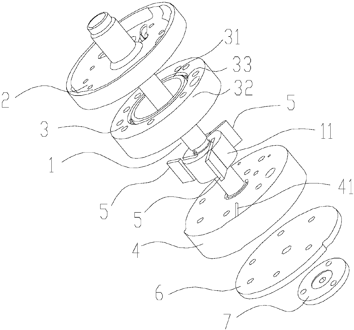
[0080] This embodiment is a further improvement made on the basis of Embodiment 1-3, preferably, it also includes a lower flange 4, and a lower oil groove that can communicate with the rolling body is also opened on the lower flange 4 41 , through the lower oil groove 41 , the oil can be led out from the lower flange 4 , or the oil can be led out from the rolling bearing 3 . Through the lower oil groove provided on the lower flange, the oil can be transported and diverted, and the lubricating oil can be discharged into the shell of the compressor, thereby realizing the recovery and recycling of the oil.
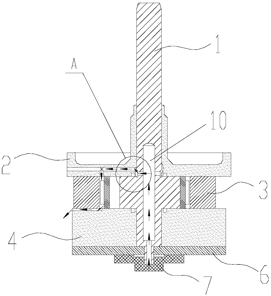
[0081] Then, after the lubricating oil passes through the rolling elements, it will flow to the lower flange due to its own gravity and oil pressure, and concentrate on the lower oil groove of the lower flange (such as Figure 8 As shown), the lower oil groove directly leads to the outside of the pump body, and the oil will flow out to the casing oil pool along with the oil o...
PUM
 Abstract
Description
Claims
Application Information
 - R&D
- Intellectual Property
- Life Sciences
- Materials
- Tech Scout
- Unparalleled Data Quality
- Higher Quality Content
- 60% Fewer Hallucinations
Browse by: Latest US Patents, China's latest patents, Technical Efficacy Thesaurus, Application Domain, Technology Topic, Popular Technical Reports.
© 2025 PatSnap. All rights reserved.Legal|Privacy policy|Modern Slavery Act Transparency Statement|Sitemap|About US| Contact US: help@patsnap.com