
Warming furnace

A heating furnace and flue pipe technology, which is applied in the field of heating furnaces, can solve the problems of low heat exchange efficiency of biomass heating furnaces, and achieve the effects of improving heat release efficiency, smoothness, and release efficiency

Pending Publication Date: 2018-02-16
威海腾罡智能科技有限公司
View PDF5 Cites 2 Cited by
  • Summary
  • Abstract
  • Description
  • Claims
  • Application Information

AI Technical Summary

Problems solved by technology

[0003]However, biomass heating stoves generally have low heat exchange efficiency, and a certain amount of ash particles are produced during the combustion process, which has become a problem that biomass heating stove manufacturers need to solve

Method used


Image

  • Warming furnace
  • Warming furnace
  • Warming furnace

Examples


Embodiment 1

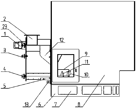
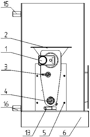
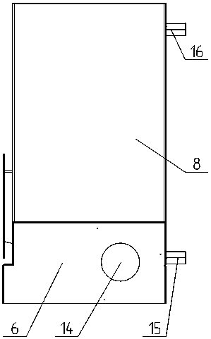
[0028] Embodiment 1: A heating furnace, including a feeding mechanism, a combustion mechanism and a smoke pipe 19, the feeding mechanism at least includes a feeding port 2, the feeding port 2 is connected to a feeding pipeline 12, and the end of the feeding pipeline 12 is connected to a combustion mechanism The combustion mechanism includes a combustion chamber 9, an air inlet pipe 13 is installed at the bottom of one side of the combustion chamber 9, a smoke pipe 19 is distributed above the combustion chamber 9, and an ash box 6 is below the combustion chamber 9; the combustion chamber The outside of 9 is covered with water tank 8.

Embodiment 2

[0029] Embodiment 2: a heating furnace, including a feeding mechanism, a combustion mechanism and a smoke pipe 19, the feeding mechanism at least includes a feeding port 2, the feeding port 2 is connected to a feeding pipeline 12, and the end of the feeding pipeline 12 is connected to a combustion mechanism The combustion mechanism includes a combustion chamber 9, an air inlet pipe 13 is installed at the bottom of one side of the combustion chamber 9, a smoke pipe 19 is distributed above the combustion chamber 9, and an ash box 6 is below the combustion chamber 9 and the smoke pipe 19; The outside of the combustion chamber 9 and the smoke pipe 19 is covered with a water tank 8 .

Embodiment 3

[0030] Embodiment 3: A heating furnace, wherein the feeding device further includes a screw feeding mechanism 17, the screw feeding mechanism 17 is located at the connection between the feeding port 2 and the feeding pipeline 12, and the screw feeding mechanism 17 is powered by the driving device 1. The feeding pipe 12 is composed of two pipes with a rectangular cross section, and the connection position of the two pipes with a rectangular cross section is a smooth transition. A screw propeller 10 is also installed in the combustion chamber 9, and the screw propeller 10 is connected with a power device or a transmission device through a transmission shaft. The screw pusher 10 is connected with the power gear 23 on the driving device 1 by a chain through the transmission gear 4 at the end of the transmission shaft. A tightening gear 3 is also installed between the transmission gear 4 and the power gear 23 . The structures and connections of the remaining parts are the same as ...


PUM


Abstract

The invention discloses a warming furnace, and belongs to the field of warming devices. The warming furnace is used for burning biomass to make people warm and includes a feeding mechanism, a combustion mechanism and a smoke pipe. The feeding mechanism at least includes a feeding hole, the feeding hole is connected with a feeding pipeline, the tail end of the feeding pipeline is connected with thecombustion mechanism, the combustion mechanism includes a combustion chamber, the bottom of one side of the combustion chamber is provided with an air inlet pipe, the smoke pipe is arranged above thecombustion chamber, and an ash box is arranged below the combustion chamber and / or the smoke pipe; a water box covers the outer part of the combustion chamber and / or the smoke pipe. According to thetechnical scheme, the system can achieve full combustion of biomass particles, the heat transfer efficiency is improved, the number of particles contained in smoke is reduced, and the environmental protection performance is improved.

Description

technical field [0001] The invention belongs to the field of heating devices, and in particular relates to a heating furnace for burning environmentally friendly fuels such as biomass particles. Background technique [0002] For a long time, in the cold winter, except for the central heating area, people rely on coal or gas for heating, but coal and gas are non-renewable resources, and a certain amount of harmful gas will be produced during the combustion process. pollute the atmosphere. With the improvement of people's awareness of environmental protection, the phenomenon of using non-renewable resources such as coal for heating in winter in non-central heating areas has gradually decreased, and it has been replaced by the use of renewable biomass particles for heating or electric heating. Electric heating consumes more electricity, costs more, and has a narrower scope of application, while biomass heating stoves use renewable biomass particles, which generate more heat du...

Claims


Application Information

Patent Timeline
Patent Type & Authority Applications(China)
IPC IPC(8): F23K3/14F23J1/06F23J11/00F23J15/02
CPCF23J1/06F23J11/00F23J15/022F23K3/14F23K2203/102F23K2203/20
Inventor 张德政
Owner 威海腾罡智能科技有限公司
Learn More