Inflation lead integral gas blasting device

An integrated, gas technology, applied in the field of blasters, can solve the problems of low heat absorption efficiency, high manufacturing cost, and low heat release efficiency of liquid carbon dioxide

Inactive Publication Date: 2017-05-10
郭远军
View PDF2 Cites 2 Cited by
  • Summary
  • Abstract
  • Description
  • Claims
  • Application Information

AI Technical Summary

Problems solved by technology

[0006] Adopt the gas blaster of above-mentioned detonator structure, existing problem is: 1, the thermal reaction material that needs to fill in the detonator needs to carry out the processing of processes such as material mixing, mixing evenly, rolling material or bagging, filling process It is time-consuming and labor-intensive, and the manufacturing cost is high; 2. During the filling process of the detonator, the oxidant and reducing agent are prone to uneven mixing, resulting in low heat release efficiency; 3. The thermal reaction material needs to be mixed and filled in advance. If the medium temperature is too high, it will easily cause combustion or explosion, which has great potential safety hazards; 4. Due to the damp, deterioration or deformation of the detonating material, it is easy to cause squibs, and it is impossible to determine the cause of the squibs, so it cannot pass The squib method eliminates potential safety hazards; 5. The detonation method of the existing gas blaster uses a solid activator to burn to generate high temperature, which directly conducts heat to the liquid carbon dioxide, causing the liquid carbon dioxide to gasify and expand, and the heat absorption efficiency of the liquid carbon dioxide is low; 6. The detonator The heat release rate is slow, the chemical reaction is insufficient, the heat release efficiency is low, the pressure of the liquid is relatively small after gasification, and the blasting power is small; 7. After the blasting, the reactants in the detonator produce a large amount of toxic and harmful gases. , such as hydrogen sulfide, sulfur dioxide, nitrogen monoxide, nitrogen dioxide and other gases, bring relatively large poisonous pollution to the blasting site
[0008] Yet the weak point that liquid oxygen explosive exists is: 1, it can only be used in open-air operation and building road and bridge, blasting building etc. If it overflows, it will cause pit gas and coal dust explosions in the mine and cause accidents; 2. Liquid oxygen explosives must be used as soon as they are installed, generally within one hour after they are made, otherwise the liquid oxygen will lose its effectiveness when it volatilizes; 3. The charging operation of liquid oxygen explosive is complicated and the safety is poor; 4. The blasting temperature of liquid oxygen explosive is too high, which is easy to cause combustion
[0011] According to the structural description of the above-mentioned existing gas blaster, it can be seen that two holes need to be opened in the plugging head with the gas charging and lead wire structure, which are respectively the filling port for filling and discharging the easily vaporized liquid and the lead wire for leading out the lead wire The problem of adopting this kind of structure is: 1. The plugging head with inflatable and lead wire structure, in the drilling process, the process is more complicated, labor-consuming and time-consuming. Larger, the sealing process is more difficult, and the problem of air leakage is prone to occur. If the hole diameter is small, the drilling will be larger and the drilling cost will be higher; 2. The lead hole needs to be filled with sealant, which is cured after sealing, and It is easy to cause deflation under high pressure; 3. High manufacturing cost

Method used


Image

  • Inflation lead integral gas blasting device
  • Inflation lead integral gas blasting device
  • Inflation lead integral gas blasting device

Examples


Embodiment 1

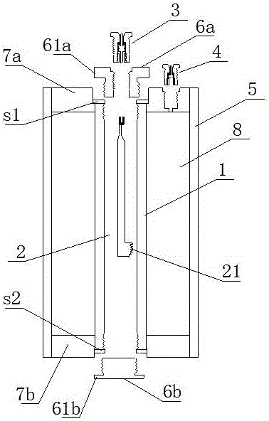
[0112] An inflatable fuse integrated gas explosion device, such as figure 1 As shown, it includes an inner tube 1, an inner tube filling cavity 2, an inner tube inflatable conductive head 3, an outer tube inflatable head 4 and an outer tube 5. The inner tube 1 is an inner tube filling cavity 2, and the two ends of the inner tube 1 are respectively A first sealing inner cover 6a and a second sealing inner cover 6b are hermetically connected, the outer layer of the inner tube 1 is an outer tube 5, and a first sealing outer cover 7a and a second sealing outer cover 7a and a second sealing cover are hermetically connected between the inner tube 1 and the outer tube 5. The outer cover 7b, the first sealed outer cover 7a and the second sealed outer cover 7b are located at both ends of the outer tube 5; the inner tube inflatable conductive head 3 is installed on the first sealed inner cover 6a; the outer tube inflatable head 4 is installed In the first sealing outer cover 7a; the sea...

Embodiment 2

[0127] The difference with embodiment 1 is: as Figure 6 As shown, the inner tube 1 is a composite layer tube containing fiber material, and the inner tube 1 includes: a matrix layer 101, a fiber layer 102, and a hardened layer 103 from the inside to the outside; one end of the inner tube 1 is sealed. Wrapped with a first metal joint 111, the other end of the inner tube 1 is sealed and wrapped with a second metal joint 112, the first metal joint 111 is connected to the first sealed inner cover 6a, and the second metal joint 112 is connected to the second sealed inner cover 6b; Bottoms of the first metal joint 111 and the second metal joint 112 protrude outward to avoid falling off from the inner tube 1 .

[0128] As a further description of the above embodiment, the base layer 101 is made of polyethylene (PE); the fiber layer 102 is made of glass fiber; the hardened layer 103 is made of epoxy resin.

[0129] As a further description of the above embodiment, the implementation...

Embodiment 3

[0133] The difference with embodiment 1 is: as Figure 7 As shown, the outer tube 5 is a composite tube containing fiber material, the outer tube 5 includes an outer tube sealing base layer 501 and an outer tube fiber layer 502 distributed inside and outside, one end of the outer tube 5 is connected with a first winding joint 511, the outer tube 5 The other end of the pipe 5 is connected with a second winding joint 512;

[0134] The top of the outer wall of the first winding joint 511 is provided with a first hanger 5111 for winding fibers, and the top of the outer wall of the second winding joint 512 is provided with a second hanger 5121 for winding fibers. The bottom of the outer wall is provided with a first boss 5112 for connecting the outer tube sealing base 501 , and the bottom of the outer wall of the second winding joint 512 is provided with a second boss 5122 for connecting the outer tube sealing base 501 .


PUM

PropertyMeasurementUnit
compressive strengthaaaaaaaaaa
thicknessaaaaaaaaaa
thicknessaaaaaaaaaa

Abstract

The invention discloses an inflation lead integral gas blasting device. The device comprises an inner pipe, an inner pipe filling cavity, an inner pipe inflation electric conducting head, an outer pipe inflation head and an outer pipe; the inner pipe filling cavity is in the inner pipe; two ends of the inner pipe are tightly connected with a first sealing inner cover and a second sealing inner cover; the outer layer of the inner pipe is the outer pipe; a first sealing outer cover and a second sealing outer cover are tightly connected between the inner pipe and the outer pipe; the inner pipe inflation electric conducting head is mounted on the first sealing inner cover or the second sealing inner cover; the outer pipe inflation head is mounted on the first sealing outer cover or the second sealing outer cover; an outer pipe filling cavity is a sealing cavity between the inner pipe and the outer pipe; an electric heating wire is mounted in the inner pipe filling cavity; supercritical oxygen and carbon-contained organic matters are filled in the inner pipe filling cavity; and such liquid-state gasified matters as liquid-state carbon dioxide or liquid-state nitrogen are filled in the outer pipe filling cavity. The inflation lead integral gas blasting device has the advantages of low production cost, high mixing uniformity of reaction materials, high heat releasing efficiency, good transportation safety and high blasting power.

Description

technical field [0001] The invention belongs to the technical field of blasters, in particular to an integrated gas blasting device with an inflatable lead wire. Background technique [0002] Gas blasting technology is to use the vaporization and expansion of easily vaporized liquid or solid substances to generate high-pressure gas, which makes the surrounding medium expand to do work and cause fragmentation. It has the characteristics of no open flame, safety and high efficiency. [0003] Carbon dioxide gas blasters are typical blasting equipment in gas blasting technology, and are widely used in mining, geological exploration, cement, steel, electric power and other industries, subways and tunnels, municipal engineering, underwater engineering, and emergency rescue. [0004] The existing gas blaster mainly includes a vaporization liquid storage pipe and a heating detonator installed in the vaporization liquid storage pipe; the heating detonator ignites and generates heat t...

Claims


Application Information

Patent Timeline
Patent Type & Authority Applications(China)
IPC IPC(8): F42B3/04F42B3/28F42B3/10F42B3/103F42B3/11F42B3/18C06D5/10C06B33/00C06B47/12C06B47/06C06B47/02C06B27/00
CPCC06B27/00C06B33/00C06B47/02C06B47/06C06B47/12C06D5/10F42B3/045F42B3/10F42B3/103F42B3/11F42B3/18F42B3/28Y02P20/10Y02P20/54
Inventor 郭远军
Owner 郭远军
Why Eureka
Try Eureka