
Water cooling radiating system and method of heat generating equipment

A heat-generating equipment, water-cooling heat dissipation technology, applied to lighting and heating equipment, water shower coolers, heat exchanger types, etc., can solve problems such as waste, uneven spraying, etc., and achieve the effect of improving cooling efficiency and heat dissipation effect

Inactive Publication Date: 2018-02-16
无锡远及科技有限公司
View PDF0 Cites 3 Cited by
  • Summary
  • Abstract
  • Description
  • Claims
  • Application Information

AI Technical Summary

Problems solved by technology

[0002] Heating equipment often needs cooling towers to cool. The fields that use cooling towers for cooling include injection molding, tanning, foaming, power generation, casting, heat treatment, steam turbines, aluminum profile processing, air compressors, industrial water cooling and other fields. The most widely used is Air-conditioning cooling, refrigeration, plastic chemical industry, flue gas spray absorption and chemical medium spray, etc., the existing cooling tower mainly adopts the form of cooling packing to dissipate heat, and uses the principle of water evaporation to cool down. The temperature of the water is relatively high, and direct spraying on the packing layer will cause a large amount of water to evaporate, resulting in waste. When the cooling water is directly sprayed on the packing layer, it is easy to cause uneven spraying

Method used


Image

  • Water cooling radiating system and method of heat generating equipment
  • Water cooling radiating system and method of heat generating equipment
  • Water cooling radiating system and method of heat generating equipment

Examples


Embodiment Construction

[0047] The present invention will be further described below in conjunction with the accompanying drawings.

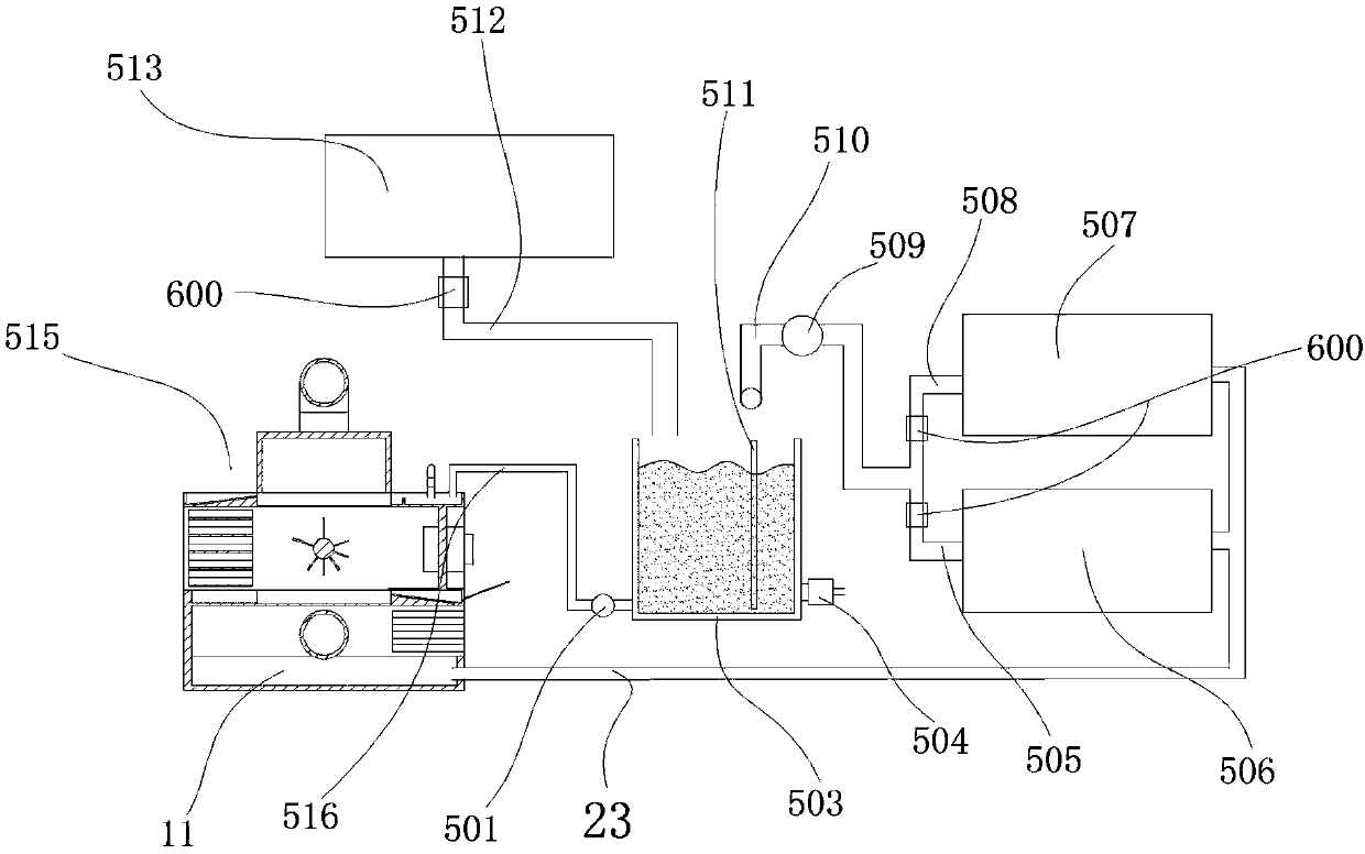
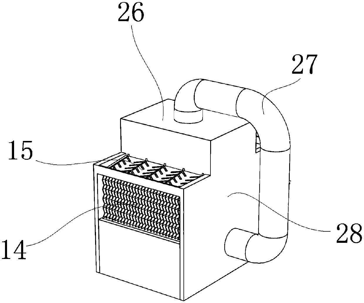
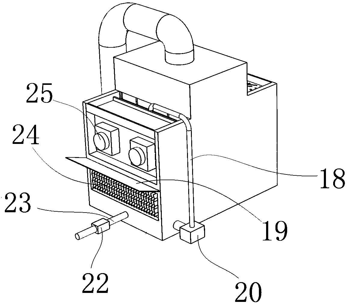
[0048] Such as figure 1 As shown, a water-cooled heat dissipation system for heating equipment is characterized in that it includes a first heating equipment to be cooled 506, a second heating equipment to be cooled 507, a cooling tower 515 and a water storage tank 503; the cold water outlet of the cooling tower 515 It is connected to the water inlet end of the cold water outlet pipe 23, and the two water outlet ends of the cold water outlet pipe 23 are respectively connected to the water inlet ends of the first heating device to be cooled 506 and the second heating device to be cooled 507; the first heating device to be cooled 506 and the hot water outlet end of the second heat generating equipment to be cooled 507 are respectively connected to the hot water outlet pipe 510 through the first header 505 and the second header 508; the outlet end of the hot water outlet ...


PUM


Abstract

The invention discloses a water cooling radiating system of heat generating equipment. The water cooling radiating system comprises first cooling-requiring heat generating equipment, second cooling-requiring heat generating equipment, a cooling tower and a water storage tank. A cold water outlet end of the cooling tower is connected with a water inlet end of a cold water outlet pipe, and two wateroutlet ends of the cold water outlet pipe are connected with water inlet ends of the first cooling-requiring heat generating equipment and the second cooling-requiring heat generating equipment correspondingly. A water outlet end of a hot water outlet pipe is correspondingly formed over the water storage tank, and a water outlet end of the bottom of the water storage tank is connected with a water inlet trough in the water inlet end of the cooling tower through a water inlet pipe of the cooling tower. In the cooling tower, before to-be-cooled water is subjected to packing evaporation cooling,primary cooling of the to-be-cooled water is achieved through a cooling water bridge mode, because water is subjected to primary cooling, water vapor generated in a next step of the packing type cooling procedure is reduced, and thus the water resource is saved.

Description

technical field [0001] The invention belongs to the field of heat dissipation, and in particular relates to a water-cooling heat dissipation system and a method for heating equipment. Background technique [0002] Heating equipment often needs cooling towers to cool. The fields that use cooling towers for cooling include injection molding, tanning, foaming, power generation, casting, heat treatment, steam turbines, aluminum profile processing, air compressors, industrial water cooling and other fields. The most widely used is Air-conditioning cooling, refrigeration, plastic chemical industry, flue gas spray absorption and chemical medium spray, etc., the existing cooling tower mainly adopts the form of cooling packing to dissipate heat, and uses the principle of water evaporation to cool down. The temperature of the water is relatively high, and direct spraying on the packing layer will cause a large amount of water to evaporate, resulting in waste. When the cooling water is...

Claims


Application Information

Patent Timeline
Patent Type & Authority Applications(China)
IPC IPC(8): F28C1/00F28F25/08
CPCF28C1/00F28F25/082F28F25/087
Inventor 丁安君
Owner 无锡远及科技有限公司
Learn More