
Interferometric fiber optic hydrophone probe for array

An optical fiber hydrophone and interferometric technology, applied in the field of sensors, can solve the problems affecting the length and thickness of the probe, poor maneuverability and flexibility, large size of a single device, etc., to achieve reliable fixation, save space, and small volume. Effect

Active Publication Date: 2018-02-16
BEIJING INST OF AEROSPACE CONTROL DEVICES
View PDF9 Cites 8 Cited by
  • Summary
  • Abstract
  • Description
  • Claims
  • Application Information

AI Technical Summary

Problems solved by technology

At present, there are some problems in the interferometric fiber optic hydrophone that hinder its miniaturization. For example, the minimum bending diameter of the optical fiber used in the Michelson interferometer is 15mm, which limits the minimum size of the probe to be greater than 15mm; there are relatively many optical devices, Moreover, the volume of a single device is too large, resulting in a relatively large size of the device compartment, which affects the overall length and thickness of the probe
Therefore, when the interferometric hydrophone probes form a towed array, the array cables are bulky, poor in maneuverability and flexibility

Method used


Image

  • Interferometric fiber optic hydrophone probe for array
  • Interferometric fiber optic hydrophone probe for array
  • Interferometric fiber optic hydrophone probe for array

Examples


Embodiment Construction

[0027] In order to make the object, technical solution and advantages of the present invention clearer, the implementation manner of the present invention will be further described in detail below in conjunction with the accompanying drawings.

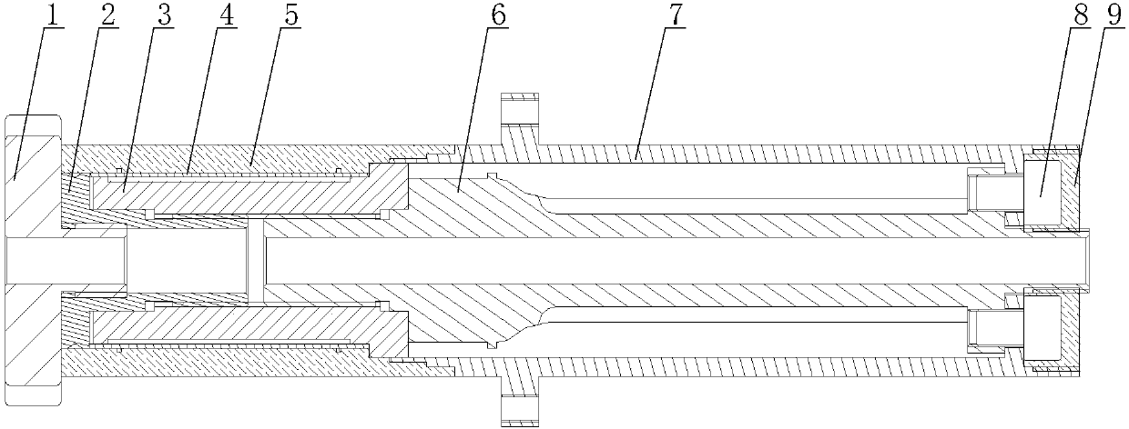
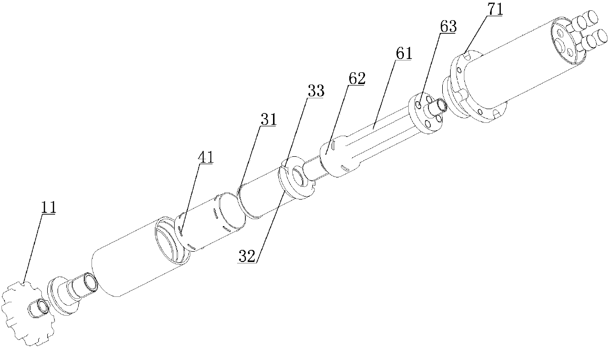
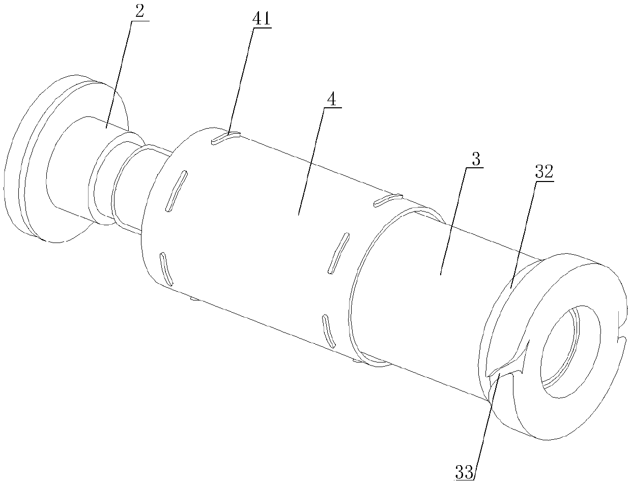
[0028] figure 1 It is a cross-sectional view of the structure of the present invention, including a protective terminal 1, a terminal 2, a support frame 3, an elastic fiber carrier tube 4, a sensitizing coating 5, an optical device placement shaft 6, a sound-proof protective sleeve 7, and a screw 8. figure 2 It is a schematic diagram of structural decomposition of the present invention, image 3 Schematic diagram of the structure of the supporting frame and the elastic fiber-carrying tube provided by the present invention.

[0029] Both the protective terminal 1 and the terminal 2 are made of stainless steel, and the protective terminal 1 and the terminal 2 are fixedly connected by screwing; the protective terminal 1 is provided with...


PUM


Abstract

An interferometric fiber optic hydrophone probe for an array comprises a protection tip, a tip, a sensitization coating, an elastic fiber carrying cylinder, a support skeleton, an optical device placing shaft, a sound insulation protection sleeve, screws and glue injection grooves. The protection tip, the tip, the sensitization coating, the elastic fiber carrying cylindes and the support skeletonform a sound wave pickup portion of the probe, and the sound wave pickup portion of the probe is used for carrying and protecting sensitive optical fibers and is good in hydrophobicity and sonolucency. The optical device placing shaft, the sound insulation protection sleeve and the glue injection grooves form a protection portion of a probe optical device, and the protection portion of the probe optical device is good in pressure resistance. Bend insensitive fibers with small bending diameters and an optical device with a small size are selected for the probe, an optical device placing structure in a marble pillar form is employed, and a fixing flange is designed on the sound insulation protection sleeve. The interferometric fiber optic hydrophone probe for an array greatly saves space usage of an optical device, achieves miniaturization of a probe, enables the volume of the fiber optic hydrophone to be smaller when the fiber optic hydrophone organizes an array, and is higher in maneuverability.

Description

technical field [0001] The invention belongs to the field of sensors, and relates to an interference type optical fiber hydrophone probe used for an array. Background technique [0002] Optical fiber hydrophone is an underwater acoustic signal sensor based on optical fiber and optoelectronic technology. As a new type of underwater acoustic detection device, compared with traditional piezoelectric hydrophones, it has high The advantages of bandwidth, anti-electromagnetic interference, passive detection of underwater wet ends and easy large-scale formation have become an important direction for the development of underwater acoustic detection technology, and have important applications in military and civilian fields. Optical fiber hydrophones can be divided into interference type, intensity type, grating type, etc., among which the development of interference type is relatively mature. Interferometric hydrophones are based on the principle of Michelson interferometers: the l...

Claims


Application Information

Patent Timeline
Patent Type & Authority Applications(China)
IPC IPC(8): G01H9/00
CPCG01H9/004
Inventor 郑百超侯振兴于文鹏王学锋张海岩张磊王海亮郝良彬李振赵俊鹏赵晨
Owner BEIJING INST OF AEROSPACE CONTROL DEVICES
Learn More