
Local-area joint-dimension-reduction range ambiguity clutter suppression method based on FDA-MIMO radar

A clutter suppression and distance ambiguity technology, which is applied in the radar field, can solve the problems of detection performance degradation, a large amount of training data, and a large amount of calculation, so as to improve detection performance, reduce calculation amount, and reduce calculation complexity.

Inactive Publication Date: 2018-02-16
XIDIAN UNIV
View PDF8 Cites 31 Cited by
  • Summary
  • Abstract
  • Description
  • Claims
  • Application Information

AI Technical Summary

Problems solved by technology

However, this method requires a large amount of calculation and requires a large amount of training data, which is difficult to apply in actual situations.
[0004] D.Cristallini et al. introduced a direct data domain in the paper "A robust direct data domain approach for STAP" (IEEE Trans.Signal Process., vol.60, no.3, pp.1283-1294, Mar.2012) The STAP method obtains second-order training samples through the smoothing of a single snapshot in the space and time domains to suppress range ambiguity clutter, but this method sacrifices a certain degree of freedom, resulting in a decline in detection performance

Method used


Image

  • Local-area joint-dimension-reduction range ambiguity clutter suppression method based on FDA-MIMO radar
  • Local-area joint-dimension-reduction range ambiguity clutter suppression method based on FDA-MIMO radar
  • Local-area joint-dimension-reduction range ambiguity clutter suppression method based on FDA-MIMO radar

Examples


Embodiment Construction

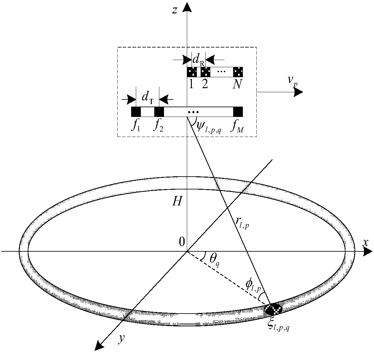
[0031] The used front side looking airborne FDA-MIMO radar model of the present invention is as figure 2 As shown, the origin O of the coordinate system is the projection point of the platform on the horizontal plane, the transmitting array and the receiving array both adopt a uniform linear array, the number of transmitting antenna array elements is M, and the number of receiving antenna array elements is N, d T is the element spacing of the transmitting antenna, d R is the spacing between receiving antenna elements, and the x-axis is the platform movement speed υ p direction, H is the height of the platform, θ q is the azimuth angle of the clutter point, φ l,p is the pitch angle of the clutter point, r l,p is the distance from the clutter point to the platform, ψ l,p,q is the angle between the clutter point and the platform, ξ l,p,q is the scattering coefficient of the clutter point.

[0032] refer to figure 1 , the specific implementation steps of the present invent...


PUM


Abstract

The invention discloses a local-area joint-dimension-reduction range ambiguity clutter suppression method based on an FDA-MIMO radar so that problems that the existing range ambiguity clutter suppression method has the poor detection performance, the operation load is high, and the requirement on the independent and identically distributed samples is high can be solved. The method comprises: stepone, carrying out matching and filtering on echo data of a radar by using a transmitting waveform; step two, carrying out range dependence compensation on the matched filtered data; step three, constructing a local-area joint dimension reduction matrix and performing dimension reduction on the received data; step three, on the basis of data after dimension reduction, estimating a clutter covariance matrix; step four, on the basis of a minimum variance, non-distortion response to a wave beam forming device is carried out to obtain an optimal weight vector; step five, carrying out weighting on the data after dimension reduction by using an optimal weight, suppressing a range ambiguity clutter, and detecting a target signal. Compared with the existing range ambiguity clutter suppression method, the provided method has the following advantages: the computing complexity is low; the requirement on the independent and identically distributed samples is low; and the clutter suppression performance is good. The range ambiguity clutter suppression on an airborne radar is realized. The method can be applied to ground moving target detection of an airborne radar.

Description

technical field [0001] The invention belongs to the technical field of radar, in particular to a range fuzzy clutter suppression method, which can be used for detecting moving targets. Background technique [0002] When the airborne early warning radar is in the looking-down working state, the clutter Doppler will spread, causing the weak target signal to be submerged by the clutter. Space-time two-dimensional adaptive processing STAP joint space and time two-dimensional information can effectively improve the ability of clutter suppression and the performance of moving target detection. The traditional STAP method assumes that there is no range ambiguity. When range ambiguity occurs, the target has to compete with both unambiguous and ambiguous clutter, which greatly reduces the detection performance of STAP. [0003] T.B.Hale et al. in the paper "Localized three-dimensional adaptive spatial-temporal processing for airborne radar" (IEE Radar Sonar and Navig., vol.150, no.1...

Claims


Application Information

Patent Timeline
IPC IPC(8): G01S7/292G01S7/42G01S13/50
CPCG01S7/2923G01S7/42G01S13/50
Inventor 许京伟廖桂生徐义正张玉洪兰岚娄联章
Owner XIDIAN UNIV
Learn More