
Semiconductor laser fast-axis collimation equipment

A technology of collimation equipment and lasers, which is applied in the direction of semiconductor lasers, semiconductor laser optical devices, lasers, etc., can solve the problems of large divergence angle, low collimation accuracy, and low efficiency, so as to improve production efficiency and avoid frequent operations Effect

Pending Publication Date: 2018-02-16
SHENZHEN JPT OPTO ELECTRONICS CO LTD
View PDF0 Cites 11 Cited by
  • Summary
  • Abstract
  • Description
  • Claims
  • Application Information

AI Technical Summary

Problems solved by technology

Due to the large divergence angle of the laser light-emitting chip on the fast axis, in order to effectively ensure the luminous quality of the semiconductor laser, it is necessary to use the fast-axis lens to collimate the light beam emitted by the light-emitting chip on the fast axis. The existing fast-axis collimation process is generally It is done manually, which leads to problems such as low accuracy and low efficiency of collimation

Method used


Image

  • Semiconductor laser fast-axis collimation equipment
  • Semiconductor laser fast-axis collimation equipment
  • Semiconductor laser fast-axis collimation equipment

Examples


Embodiment Construction

[0024] In order to facilitate the understanding of the present invention, the following will describe the present invention more fully. However, the present invention can be embodied in many different forms and is not limited to the embodiments described herein. On the contrary, these embodiments are provided to make the understanding of the disclosure of the present invention more thorough and comprehensive.

[0025] Unless otherwise defined, all technical and scientific terms used herein have the same meaning as commonly understood by one of ordinary skill in the technical field of the invention. The terms used herein in the description of the present invention are for the purpose of describing specific embodiments only, and are not intended to limit the present invention.

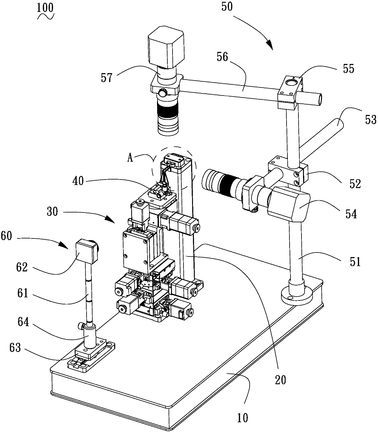
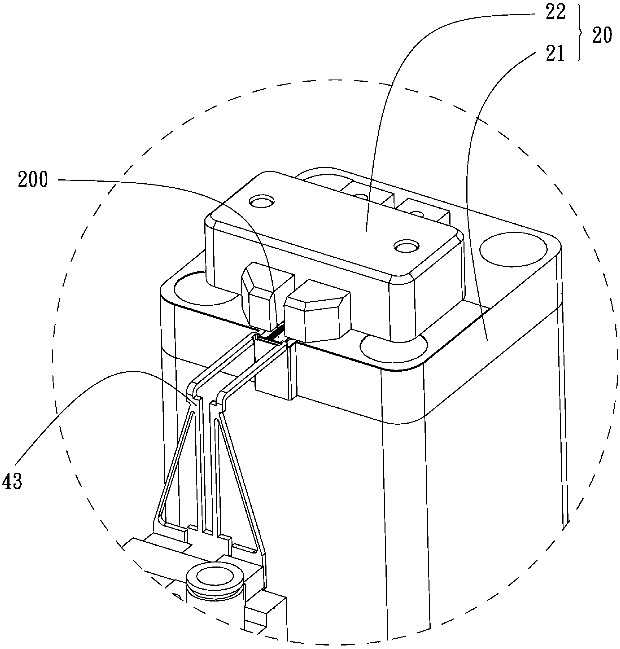
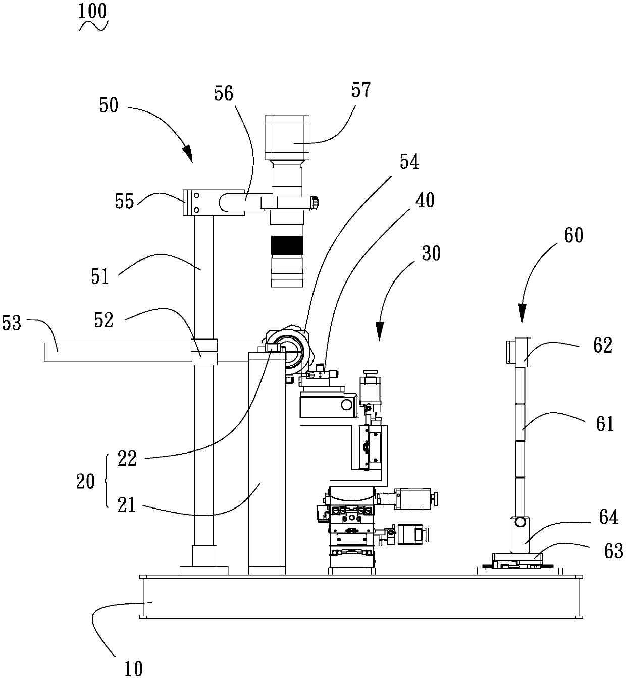
[0026] see Figure 1 to Figure 8 , is a semiconductor laser fast-axis collimation device 100 according to a preferred embodiment of the present invention, which is used to adjust the position and angle...


PUM


Abstract

The invention discloses semiconductor laser fast-axis collimation equipment used for adjusting the position and angle of a fast-axis lens so as to perform fast-axis collimation on light beams emittedfrom a semiconductor laser light emitting chip. The semiconductor laser fast-axis collimation equipment comprises a substrate, a chip bearing frame mounted on the substrate, an adjustment fame mountedon the substrate, a lens clamp mounted on the adjustment frame, an image collection assembly mounted on the substrate, and an optical detection assembly mounted on the substrate; the image collectionassembly is used for identifying the position of the fast-axis lens through image detection; and the adjustment frame is used for adjusting the position and the angle of the lens clamp to enable thelaser light beams to form light spots on the optical detection assembly. The semiconductor laser fast-axis collimation equipment, by virtue of detection and analysis of the image detection assembly orthe optical detection assembly, controls the action of the adjustment frame, so that automation of the semiconductor laser fast-axis collimation can be realized, frequent manual operation is avoided,and production efficiency of the semiconductor laser is improved.

Description

technical field [0001] The invention relates to laser adjustment technology, in particular to a semiconductor laser fast axis collimation device. Background technique [0002] The beam emitted by the light-emitting chip in the semiconductor laser is a divergent elliptical beam. The direction parallel to the light-emitting surface is the slow axis, and the divergence angle is about 10°. The direction perpendicular to the light-emitting surface is the fast axis direction, and the divergence angle can reach 40°. . Due to the large divergence angle of the laser light-emitting chip on the fast axis, in order to effectively ensure the luminous quality of the semiconductor laser, it is necessary to use the fast-axis lens to collimate the light beam emitted by the light-emitting chip on the fast axis. The existing fast-axis collimation process is generally It is done manually, which leads to problems such as low accuracy and low efficiency of collimation. Contents of the inventio...

Claims


Application Information

Patent Timeline
IPC IPC(8): H01S5/00
CPCH01S5/005
Inventor 文少剑刘猛廖东升
Owner SHENZHEN JPT OPTO ELECTRONICS CO LTD
Learn More