
Double-headed milling cutter structure

A technology of milling cutter and cutter head, which is applied in the field of double-end milling cutter structure and milling cutter structure, can solve the problem that the two cutter heads cannot be split, and achieve the effects of cost saving, production cost reduction and material saving

Inactive Publication Date: 2018-02-23
常州市飞尔达工具有限公司
View PDF0 Cites 0 Cited by
  • Summary
  • Abstract
  • Description
  • Claims
  • Application Information

AI Technical Summary

Problems solved by technology

[0003] The two heads of the current double-ended milling cutter cannot be disassembled, and can only be used for a specific milling machine tool. In actual milling operations, the cooperation between the single-ended milling cutter and the double-ended milling cutter is required, so the milling cutter is required With higher adjustability

Method used


Image

  • Double-headed milling cutter structure
  • Double-headed milling cutter structure
  • Double-headed milling cutter structure

Examples


Embodiment Construction

[0016] The following will clearly and completely describe the technical solutions in the embodiments of the present invention with reference to the accompanying drawings in the embodiments of the present invention. Obviously, the described embodiments are only some, not all, embodiments of the present invention. Based on the embodiments of the present invention, all other embodiments obtained by persons of ordinary skill in the art without making creative efforts belong to the protection scope of the present invention.

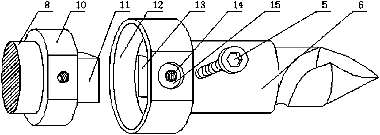
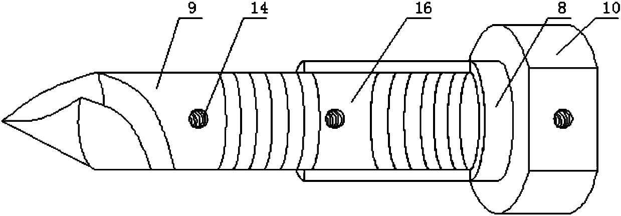
[0017] see Figure 1-3 As shown, a double-ended milling cutter structure includes a first cutter head 3, the side of the first cutter head 3 is provided with a cutting edge 1, and the side of the first cutter head 3 is provided with a chip removal groove 2, and the The chip flute 2 runs through the inside of the cutting edge 1; the side of the first cutter head 3 is provided with a fixing hole 14, and the inside of the first cutter head 3 is penetrated with a ...


PUM


Abstract

The invention discloses a structure of a double-ended milling cutter, which comprises a blade, a chip removal groove, a first cutter head, a first clamping groove, a fixing bolt, a first fixing handle, a first fixing ring, a second fixing handle, a second knife A head, a second fixing ring, a limiting block, a fixing groove, a limiting groove, a fixing hole, a second card groove and an accommodation space. In the double-end milling cutter structure of the present invention, the first fixed ring at the end of the first fixed handle is engaged with the second fixed ring at the end of the second fixed handle, and the limit block at the end of the second fixed ring is engaged with the first The limit groove inside the fixed ring, the fixed bolt fixes the first fixed ring and the second fixed ring, thus realizing the detachable differentiation of the double-end milling cutter, which can adapt to the requirements of more milling operations, thereby reducing the production cost ; The first cutter head is threadedly connected to the first fixed shank, and the second cutter head is threadedly connected to the second fixed shank, so that when the milling cutter is damaged and replaced, its usable part can be reserved to the greatest extent, thereby saving materials and further saving costs.

Description

technical field [0001] The invention relates to a milling cutter structure, in particular to a double-end milling cutter structure, belonging to the field of mechanical processing. Background technique [0002] A milling cutter is a rotating tool with one or more teeth for milling. When working, each knife tooth cuts off the allowance of the workpiece intermittently in turn. Milling cutters are mainly used for machining planes, steps, grooves, forming surfaces and cutting off workpieces on milling machines. A narrow margin is ground on the flank to form a relief angle. Due to the reasonable cutting angle, its life is relatively high. The tooth back of the sharp-tooth milling cutter has three forms: straight line, curved line and broken line. Straight backs are often used for fine-toothed finishing milling cutters. The teeth with curved and broken line tooth backs have better strength and can withstand heavy cutting loads, and are often used in coarse-toothed milling cutt...

Claims


Application Information

Patent Timeline
IPC IPC(8): B23C5/02
CPCB23C5/02B23C2200/32
Inventor 汤云飞
Owner 常州市飞尔达工具有限公司
Learn More