Steel pipe cutting robot

A technology for cutting robots and steel pipes, which is applied to metal sawing equipment, sawing machine devices, and sawing machine attachments, etc., can solve the problems of spark sputtering safety hazards, low processing efficiency, and complicated operations, so as to reduce safety hazards and be easy to operate. Effect

Inactive Publication Date: 2018-02-23
广西环游信息技术开发有限公司
View PDF0 Cites 1 Cited by
  • Summary
  • Abstract
  • Description
  • Claims
  • Application Information

AI Technical Summary

Problems solved by technology

[0002] Steel pipe cutting is usually a time-consuming and laborious operation. Traditionally, it is manual, and there will be uneven cutting, low processing efficiency, and poor quality. The existing cutting device is cumbersome to operate and requires manual feeding. It can only cut specific Thick and thin steel pipes cannot accurately grasp the cutting length, and sparks splashing during cutting pose a safety hazard

Method used


Image

  • Steel pipe cutting robot
  • Steel pipe cutting robot
  • Steel pipe cutting robot

Examples


Embodiment Construction

[0021] Below in conjunction with accompanying drawing and specific embodiment the present invention is described in further detail:

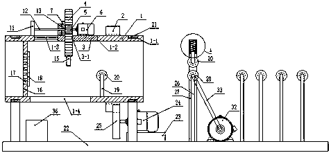
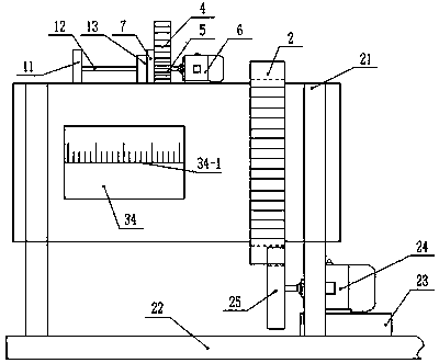
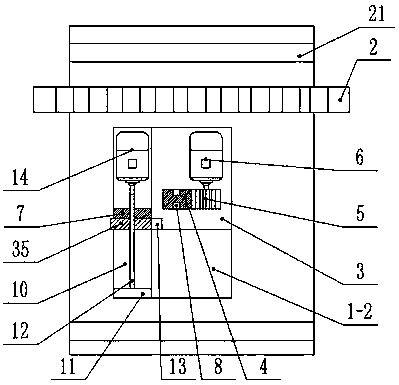
[0022] Such as figure 1 , figure 2 , image 3 , Figure 4 , Figure 5 , Figure 6 , Figure 7 and Figure 8 As shown, a steel pipe cutting robot includes a housing 1, the cross section of the housing 1 is circular, the surface of the housing 1 is provided with a plurality of annular grooves 1-1, and the upper end of the housing 1 is provided with A square through groove A1-2, the two sides of the square through groove A1-2 are provided with a chute A1-3, the surface of the housing 1 is fixed with external teeth 2, and the square through groove A1-2 is provided with Slider 3, slider B9 is fixed on both sides of the slider 3, and the slider B9 is in the chute A1-3 and is slidably connected with it. The slider 3 is provided with a square through groove B3-1, and the square through A rack 4 is provided in the groove B3-1, and a chute B4-1 i...


PUM


Abstract

The invention discloses a steel pipe cutting robot, which comprises a shell with external teeth and a square slot A, a slide plate inside the square slot A, a square slot B on the slide plate, and a rack inside the square slot B , there is a motor A and a connecting block on the slide, a gear A on the motor A, a boss on the shell, a baffle A, a baffle B and a motor B on the boss, a screw on the baffle A, and a screw on the screw. There are nuts, a blade under the rack, a top plate inside the housing, a pressure sensor on the top plate, a rubber pad on the top plate, a vertical rod A in the housing, a guide wheel on the vertical rod A, an opening under the housing, and a ring-shaped concave There is a bracket on the groove, a pad on the base, a PLC controller, a support rod A, a motor D and multiple vertical rods B, a gear B on the motor C, a sleeve on the support rod A, and a support rod B inside the sleeve And the spring, the motor D is connected with the rotating shaft belt, and there is glass on the casing. The invention is easy to operate, automatic feeding, suitable for steel pipes with different thicknesses, and reduces potential safety hazards.

Description

technical field [0001] The invention relates to the field of industrial equipment, in particular to a steel pipe cutting robot. Background technique [0002] Steel pipe cutting is usually a time-consuming and laborious operation. Traditionally, it is manual, and there will be uneven cutting, low processing efficiency, and poor quality. The existing cutting device is cumbersome to operate and requires manual feeding. It can only cut specific Thick and thin steel pipes cannot accurately grasp the cutting length, and sparks splashing during cutting pose a safety hazard. Contents of the invention [0003] In order to solve the above existing problems, the present invention provides a steel pipe cutting robot. [0004] The present invention is realized through the following technical solutions: [0005] A steel pipe cutting robot, comprising a shell, the cross-section of the shell is circular, the surface of the shell is provided with a plurality of annular grooves, the upper...

Claims


Application Information

Patent Timeline
Patent Type & Authority Applications(China)
IPC IPC(8): B23D51/02B23D51/04B23D51/16B23D59/00
CPCB23D51/025B23D51/043B23D51/046B23D51/16B23D59/001
Inventor 郭晓非
Owner 广西环游信息技术开发有限公司
Why Eureka
Try Eureka