

Welding head for laser narrow-gap welding
A narrow gap, welding head technology, applied in the field of laser narrow gap welding head, can solve the problem of no welding head and so on
Active Publication Date: 2018-02-23
BEIJING UNIV OF TECH
View PDF8 Cites 8 Cited by
- Summary
- Abstract
- Description
- Claims
- Application Information
AI Technical Summary
Problems solved by technology
In laser narrow gap welding, the welding head is the most critical factor affecting the welding process and welding quality except the laser, but there is still no welding head dedicated to laser narrow gap welding.
Method used
View moreImage
Smart ImageViewing Examples

Examples
specific Embodiment approach 2
[0026] The difference from Embodiment 1 is that the focus position, welding wire position and shielding gas nozzle position are automatically controlled by setting a motor system on the side of the moving mechanism.
Login to View More PUM
 Abstract
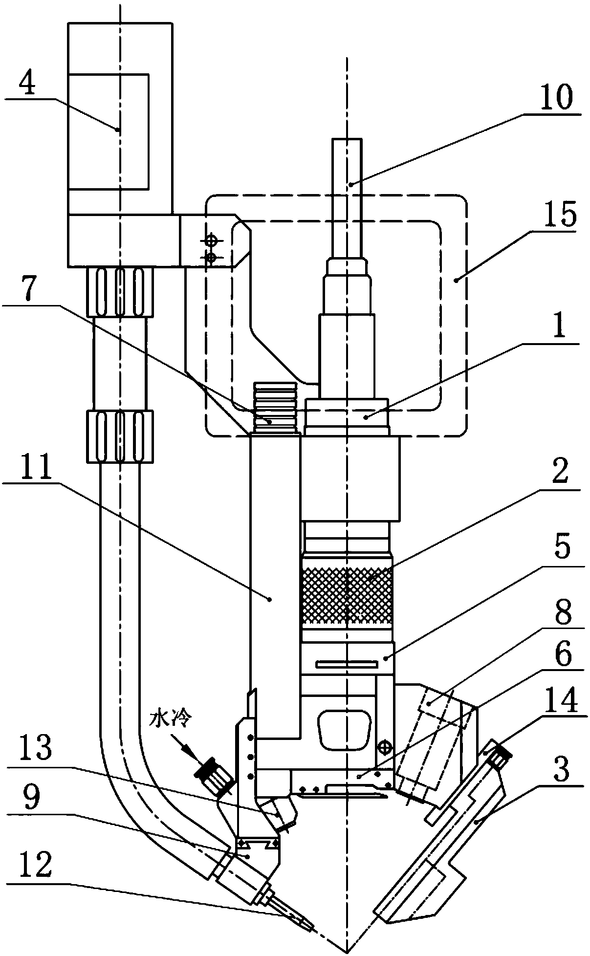
The invention relates to a welding head for laser narrow-gap welding. The welding head can be used for laser narrow-gap multi-layer welding on thick plates and can also be used for laser wire fillingwelding, laser soldering and the like. The structure of the welding head mainly comprises the main parts such as a welding head base body, a laser transmission and focusing module, a welding wire conveying module, a gas protection module, a transverse gas proof curtain and a charge coupled device observation module. During welding, movement mechanisms, such as a mechanical arm, are responsible formoving according to preset routes, the position of optical focal point and the height of the wire feeding drop point can be manually or automatically adjusted only according to the gap depth and width in each layer of welding bead, and the positions of other parts including the welding head base body, a gas protection nozzle and the charge coupled device observation module are not changed; only when the accumulated height of weld joints exceeds a certain value, the heights of the movement mechanisms are required to change, and welding can be completed by repeating the above processes. The welding head adopts a modular design, is compact in structure, and has the characteristics of being high in adaptability, high in welding efficiency and convenient to operate and maintain.
Description
technical field [0001] The invention relates to a laser narrow gap welding head, which belongs to the field of laser processing. Background technique [0002] A large number of thick-walled structures are used in nuclear power, petrochemical, shipbuilding, marine engineering and other industrial fields. Welding is one of the most critical processes in the manufacturing process of these structures, and welding is also a key link that determines production efficiency. For the welding of thick plates with large precision structures, narrow gap welding is usually selected due to strict requirements on weld quality, weld shape, welding deformation, etc. At present, the main methods of narrow gap welding are narrow gap TIG and narrow gap MIG. However, these two narrow-gap arc welding have obvious shortcomings such as large heat input, serious stress deformation of the welding structure, large metal filling due to wide gap, and low welding efficiency. With the rapid development of...
Claims
Login to View More Application Information
Patent Timeline
 Patent Type & AuthorityApplications(China)
IPC IPC(8): B23K26/21B23K26/03B23K26/14B23K26/142B23K26/70
CPCB23K26/032B23K26/14B23K26/142B23K26/21B23K26/702
Inventor杨武雄李飞武强肖荣诗
OwnerBEIJING UNIV OF TECH