
A plugging agent, plugging slurry and plugging construction method for drilling fractured leakage

A construction method and technology of plugging slurry, which is applied in the direction of drilling composition, chemical instruments and methods, earthwork drilling, etc., can solve the problems of low plugging success rate of the plugging agent, reduce the difficulty of plugging, optimize Reduced dehydration and long pumping time

Active Publication Date: 2020-03-24
中石化石油工程技术服务有限公司 +1
View PDF8 Cites 1 Cited by
  • Summary
  • Abstract
  • Description
  • Claims
  • Application Information

AI Technical Summary

Problems solved by technology

[0005] The purpose of the present invention is to provide a plugging agent for drilling fracture loss, so as to solve the problem of low leakage plugging success rate of existing plugging agents

Method used


Image

  • A plugging agent, plugging slurry and plugging construction method for drilling fractured leakage
  • A plugging agent, plugging slurry and plugging construction method for drilling fractured leakage
  • A plugging agent, plugging slurry and plugging construction method for drilling fractured leakage

Examples


Embodiment 1

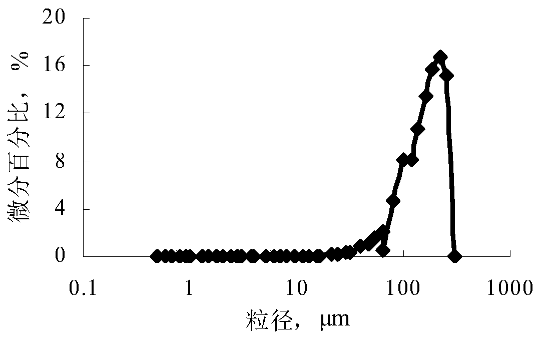
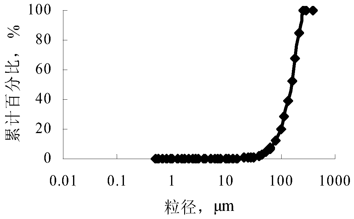
[0056] The plugging agent of this embodiment consists of the following components by weight: 84 parts of G grade cement, 8 parts of floating beads, 8 parts of micro silicon, 2 parts of asbestos fiber, 1.8 parts of fluid loss reducer, 1 part of expansion agent, 0.22 parts of retarder, 0.05 parts of potassium polyacrylate (KPAM); the cumulative percentage of cement in the particle size range of 0.68 to 63 μm reaches 93.8%; the floating beads are power plant floating beads, and the cumulative percentage in the particle size range of 0.063 to 0.256 mm reaches 95.21 %(Such as figure 1 and figure 2 shown); the cumulative percentage of micro-silicon in the particle size range of 0.04-0.68 μm reaches 97.4%; asbestos fibers are composed of short asbestos fibers with a length of 1mm≤length<3mm and long asbestos fibers with a length of 3mm≤length≤6mm in a mass ratio of 2:1 Compounded, the two types of fibers are mixtures of various lengths within their respective length ranges.

[005...

Embodiment 2

[0079]The plugging agent of this embodiment is composed of the following components by weight: 81 parts of G grade cement, 7 parts of floating beads, 10 parts of micro silicon, 1 part of asbestos fiber, 1 part of fluid loss reducer, 0.8 part of expansion agent, 0.2 parts of retarder, 0.03 parts of potassium polyacrylate (KPAM); asbestos fibers are compounded by short asbestos fibers with a length of 1mm≤length<3mm and long asbestos fibers with a length of 3mm≤length≤6mm in a mass ratio of 1.8:1.

[0080] The plugging slurry of this embodiment is made by mixing the plugging agent of this embodiment and water, and the water-cement ratio is 0.82.

Embodiment 3

[0082] The plugging agent of this embodiment is composed of the following components by weight: 85 parts of G grade cement, 10 parts of floating beads, 7 parts of micro silicon, 3 parts of asbestos fiber, 2 parts of fluid loss reducer, 1.2 parts of expansion agent, Retarder 0.28 parts, potassium polyacrylate (KPAM) 0.06 parts; asbestos fibers are compounded by short asbestos fibers with a length of 1mm≤length<3mm and long asbestos fibers with a length of 3mm≤length≤6mm in a mass ratio of 2.2:1.

[0083] The plugging slurry of this embodiment is made by mixing the plugging agent of this embodiment and water, and the water-cement ratio is 0.88.

[0084] The plugging slurry in Example 2 and Example 3 is used for the plugging construction, and the technical process can refer to Example 1, and a similar plugging effect can be obtained.


PUM

PropertyMeasurementUnit
lengthaaaaaaaaaa
particle diameteraaaaaaaaaa

Abstract

The invention relates to a plugging agent and plugging slurry for drilling fractured leakage and a plugging construction method. The plugging agent is prepared from the following components in parts by weight: 80 to 85 parts of cement, 6 to 10 parts of floating beads, 6 to 10 parts of micro-silicon and 1 to 3 parts of asbestos fibers. The plugging agent for the drilling fractured leakage, disclosed by the invention, is characterized in that the cement, the floating beads, the micro-silicon and the asbestos fibers are compounded to form a main body of the plugging agent, wherein the asbestos fibers can be used as a bridge plug for bridging to fractures; the floating beads and the micro-silicon realize filling and plugging effects on the fractures; all the components are coordinated with oneanother, so that the plugging agent easily enters a leakage layer and realizes the comprehensive effects of serving as the bridge plug, bridging, filling and plugging; the plugging agent is especially suitable for the fractured leakage with the width of 3 to 10mm and leakage rate of 5 to 100m<3>; in addition, the plugging agent has the advantages of quick plugging effects, short operation periodand high success rate of plugging leakage.

Description

technical field [0001] The invention belongs to the field of plugging of drilling leakage, and in particular relates to a plugging agent, a plugging slurry and a plugging construction method for drilling fractured leakage. Background technique [0002] When drilling encounters formation layers with geological structure characteristics such as faults, elevation angle connectivity fractures or mudstone fracture zones, due to the narrow window between the leakage pressure and the formation pressure, if the drilling fluid density control is unreasonable and the excited pressure is too large, It is easy to cause drilling loss, even malignant loss. Moreover, in the process of dealing with lost circulation, it is easy to induce wellbore instability and collapse, blowout, and drill sticking accidents, which complicate the wellbore situation. Drilling leakage or well wall collapse due to leakage will seriously affect the drilling progress, prolong the drilling cycle and increase the...

Claims


Application Information

Patent Timeline
Patent Type & Authority Patents(China)
IPC IPC(8): C09K8/42C09K8/487C09K8/467E21B33/13
CPCC09K8/426C09K8/467C09K8/487C09K2208/08C09K2208/18E21B33/13
Inventor 魏平蒋新立张冠军吴天乾席银申李明忠李德红刘福韩婧李正国
Owner 中石化石油工程技术服务有限公司
Learn More