Metal roof balance layer structure

A metal roof and balance layer technology, applied in the direction of roof covering layer, roof, roof using flat/curved panels, etc., can solve the problems of increased roof load, a large amount of lightweight debris, and a large amount of manual engineering, reducing the need for The effect of on-site operation procedures and manual engineering, good windy weather, and increased roof load

Pending Publication Date: 2018-02-23
李志民
View PDF8 Cites 2 Cited by
  • Summary
  • Abstract
  • Description
  • Claims
  • Application Information

AI Technical Summary

Problems solved by technology

[0007] (1) There are many processes, the construction is complicated, and the amount of manual work is large
[0008] (2) When the polyurethane board is selected, the flame retardant performance of the material is low (up to B2); when the rock wool board is selected, the weight of the material is larger, and the roof load increases more
[0009] (3) High cost
[0011] (5) Cushion products (polyurethane board or rock wool) are cut in small sizes, which will generate a lot of light debris on the construction site and are not easy to recycle, causing environmental pollution

Method used


Image

  • Metal roof balance layer structure
  • Metal roof balance layer structure
  • Metal roof balance layer structure

Examples


Embodiment 1

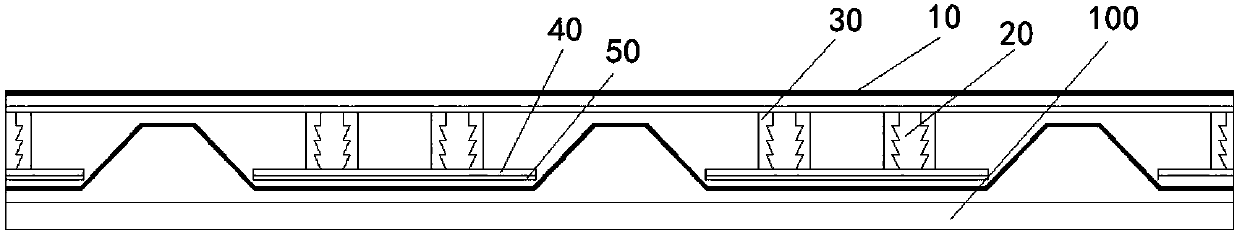
[0040] Such as Figure 2-3 As shown, the present invention provides a metal roof balance layer structure, comprising:

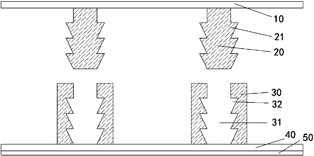
[0041] At least one top plate passes through 10, and the lower surface of the top plate through 10 is fixedly connected with a plurality of support columns passing through 20;

[0042] A plurality of bottom plate passes through 40, and the upper surface of the bottom plate through 40 passes through is fixedly connected with a plurality of limit concave post passes through 30 that are matched with the support column through 20 through one by one, so The limiting concave column passes through 30 and the support column passes through 20 through the snap connection, the size of the bottom plate passing through 40 is suitable for the size of the metal roof trough, and the bottom plate passing through 40 The lower surface of the metal roof is connected with the trough of the metal roof;

[0043] Each of the top plates passes through 10 passes through the upper su...

Embodiment 2

[0057] Such as Figure 2-3 As shown, the present invention provides a metal roof balance layer structure, comprising:

[0058] At least one top plate passes through 10, and the lower surface of the top plate through 10 is fixedly connected with a plurality of support columns passing through 20;

[0059] A plurality of bottom plate passes through 40, and the upper surface of the bottom plate through 40 passes through is fixedly connected with a plurality of limit concave post passes through 30 that are matched with the support column through 20 through one by one, so The limiting concave column passes through 30 and the support column passes through 20 through the snap connection, the size of the bottom plate passing through 40 is suitable for the size of the metal roof trough, and the bottom plate passing through 40 The lower surface of the metal roof is connected with the trough of the metal roof;

[0060] Each of the top plates passes through 10 passes through the upper su...

Embodiment 3

[0075] Such as Figure 2-3 As shown, the present invention provides a metal roof balance layer structure, comprising:

[0076] At least one top plate passes through 10, and the lower surface of the top plate through 10 is fixedly connected with a plurality of support columns passing through 20;

[0077] A plurality of bottom plate passes through 40, and the upper surface of the bottom plate through 40 passes through is fixedly connected with a plurality of limit concave post passes through 30 that are matched with the support column through 20 through one by one, so The limiting concave column passes through 30 and the support column passes through 20 through the snap connection, the size of the bottom plate passing through 40 is suitable for the size of the metal roof trough, and the bottom plate passing through 40 The lower surface of the metal roof is connected with the trough of the metal roof;

[0078] Each of the top plates passes through 10 passes through the upper su...


PUM


Abstract

The invention relates to a metal roof balance layer structure. The metal roof balance layer structure comprises a top plate and a bottom plate, wherein the lower surface of the top plate is fixedly connected with a plurality of supporting columns; the upper surface of the bottom plate is fixedly connected with limiting concave columns which are matched with the supporting columns in a one-to-one correspondence manner; the limiting concave columns are connected with the supporting columns in a clamped manner; the size of the bottom plate is matched with the sizes of troughs of a metal roof; thelower surface of the bottom plate is in adhesion connection with the troughs of the metal roof or the bottom plate is connected with structural purlines by penetrating mechanical fixing pieces into the metal roof; and the supporting columns of the bottom plate are correspondingly connected with the limiting concave columns of the bottom plate. The material of the balance layer structure is lightin specific gravity, the structural design is light, and thus, the weight is greatly reduced; materials and artificial project quantity are greatly reduced, and the cost is saved; cutting of materialson the spot is avoided, pollution-free construction is implemented, and the environmental protection performance is high; and the metal roof balance layer structure is simple in structure, and large-scale production and mounting and using are facilitated.

Description

technical field [0001] The invention relates to the field of building materials, in particular to a balance layer structure in which wave crests and wave troughs of a metal roof are built into a plane. Background technique [0002] Light roof gardens can be built on large metal roofs, thin-film solar photovoltaic modules can be installed, and graphic art can be designed and produced, but it is necessary to integrate the height difference between the peaks and troughs of metal roof panels, as well as the widespread leakage problems. [0003] Due to the increasingly expensive urban land, and considering the inherent characteristics of large metal roofs (many are located in cities or suburbs, and the building types are mostly factories, large warehouses or public buildings, they are firm, flat and have a certain load capacity, which can be used in densely populated areas. In recent years, the development and application of idle space on large metal roofs has attracted widesprea...

Claims


Application Information

Patent Timeline
Patent Type & Authority Applications(China)
IPC IPC(8): E04D3/16E04D3/36
CPCE04D3/16E04D3/36
Inventor 李志民
Owner 李志民
Why Eureka
Try Eureka