Hydraulic self-control brake device

A brake device, hydraulic technology, applied in the direction of mining fluid, axial brake, mechanical equipment, etc., can solve the problems of waste of manpower, difficult operation, inaccurate brake positioning, etc., to improve safety management level and reduce oil well failure The effect of reducing the difficulty of operation

Active Publication Date: 2021-06-29
东营恒科精密金属有限公司
View PDF7 Cites 0 Cited by
  • Summary
  • Abstract
  • Description
  • Claims
  • Application Information

AI Technical Summary

Problems solved by technology

[0002] At present, belt-type pumping units have been widely used in oil field exploitation to drive oil pumps to pump crude oil out of the ground, which has accounted for a large proportion in oil field production and application, but the wheel brake device still stays in the manual brake mode. Manual on-site operation is required, and the distance between the control cabinet and the brake operation handle is relatively long. It is difficult for one person to operate the brake and then run to the brake. The brake positioning is not accurate and the operation is difficult; It is a waste of manpower to cooperate with the accurate operation of well stop and brake. At the same time, there are also situations such as personnel neglecting, forgetting to brake, and no one arriving at the scene after remote well stop, etc., resulting in an unsafe state of well stop without braking, causing safety hazards; in addition, Failure to brake after remote shutdown will cause the pumping unit to stop at an uncertain position. When the pumping unit is restarted when the stop position does not match the well conditions such as sand production and wax deposition, failures such as oil well pump jams may occur, resulting in high maintenance costs. cost
[0003] The existing electromagnetic brake needs long-term power supply in the braking state, resulting in high energy consumption and high coil temperature, which cannot be practically applied; another hydraulic brake device powered by a hydraulic station requires a hydraulic pump to brake or release the brake. One of the states of the brakes keeps working for a long time, so the energy consumption is high, and the equipment loss is relatively large, so it is difficult to promote the use in the field

Method used


Image

  • Hydraulic self-control brake device
  • Hydraulic self-control brake device
  • Hydraulic self-control brake device

Examples


Embodiment

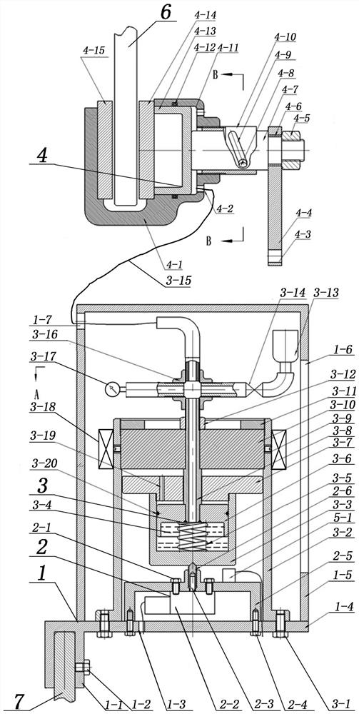
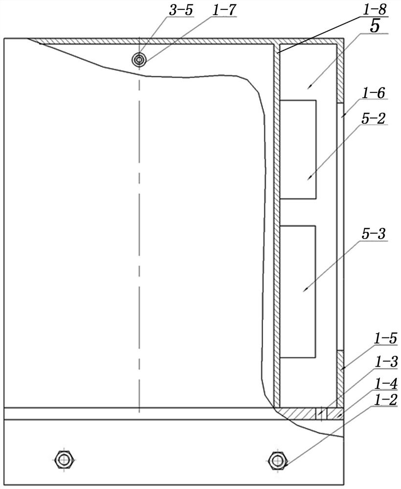
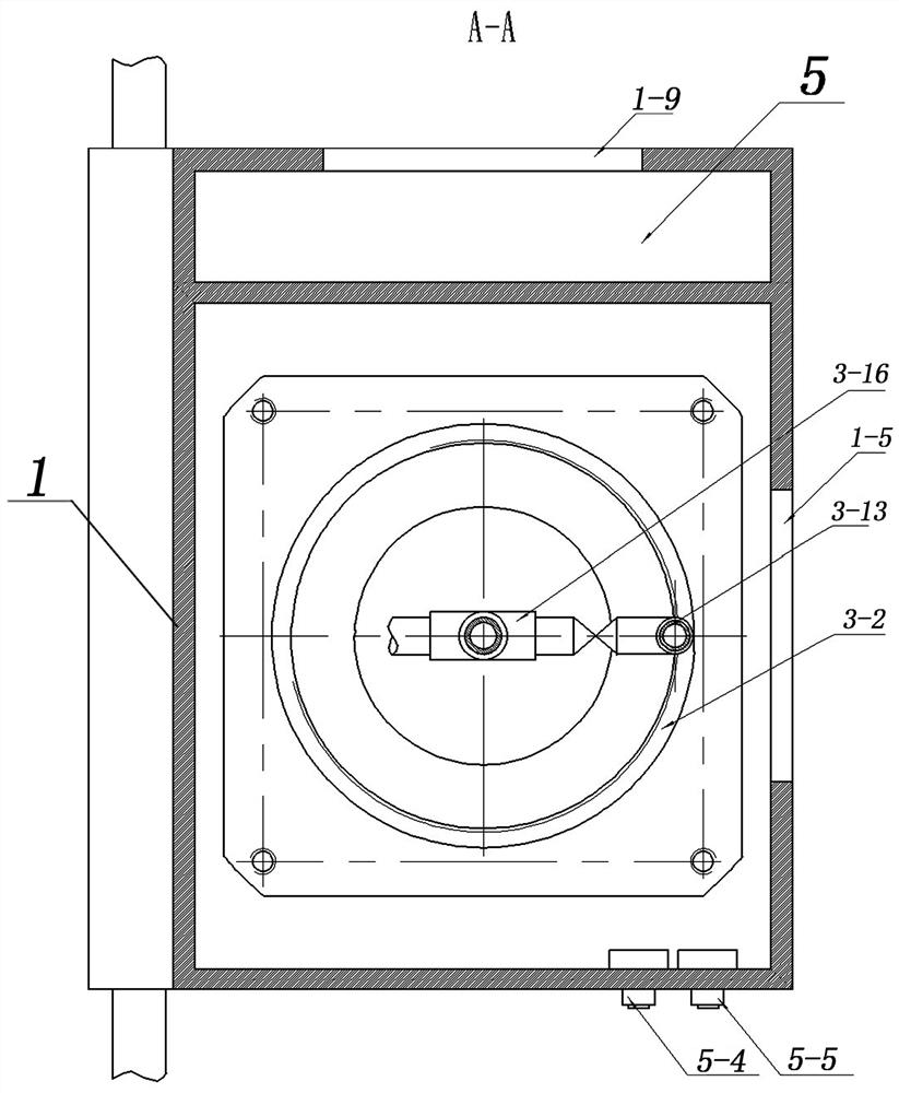
[0038] A hydraulic self-control brake device, which installs the "U" splint 1-1 of the box body 1 on the side vertical plate 7 of the pumping unit support, and fastens it with the jacking bolts Ⅰ1-2, without welding and causing no friction. The unfavorable effect of the structure of the pumping unit not only replaces all the functions of the original brake, but also realizes automatic control, and the position of stopping the well can be preset through the three-speed switch. The working process is as follows:

[0039] 1. During remote shutdown, the production command center sends a well shutdown command, which is transmitted to the oil well RTU through the communication network, and the RTU will send a pulse signal to the input terminal X1 of the PLC circuit control board 5-3, and the PLC circuit control board 5-3 enters the shutdown program , start to monitor the bottom dead point signal preset by the three-speed transfer switch, the delay point signal after the bottom dead p...


PUM


Abstract

A hydraulic self-control brake device comprises a box body, an auxiliary brake device, an electromagnetic hydraulic master cylinder, a brake cylinder and an electric chamber. The hydraulic self-control brake device is characterized in that a side door is arranged at the right wall of an outer cover of the box body, a partition plate is arranged insides, the electric chamber is arranged behind the partition plate, the electric chamber is provided with an electric chamber door, the auxiliary brake device is arranged at the lower portion of the front surface of the partition plate, the electromagnetic hydraulic master cylinder is arranged at the upper portion of the auxiliary brake device, and a supporting cylinder is arranged outside the auxiliary brake device and the electromagnetic hydraulic master cylinder; and the upper portion of the electromagnetic hydraulic master cylinder is connected with the brake cylinder through a four-way joint and a high-pressure hose. According to the hydraulic self-control brake device, the oil field production informatization technology is utilized, remote control over starting, stopping and braking is achieved, potential safety hazards caused by the fact that a pumping unit is in a free state due to the fact that personnel cannot arrive at the site or forget to brake on the site are reduced, the safety risk that the personnel go to the site to open a well is avoided under the severe weather condition, the oil field safety management level is improved, and the labor intensity of post workers is reduced.

Description

technical field [0001] The invention belongs to the technical field of mechanical braking, in particular to a hydraulic self-control braking device. Background technique [0002] At present, belt-type pumping units have been widely used in oil field exploitation to drive oil pumps to pump crude oil out of the ground, which has accounted for a large proportion in oil field production and application, but the wheel brake device still stays in the manual brake mode. Manual on-site operation is required, and the distance between the control cabinet and the brake operation handle is relatively long. It is difficult for one person to operate the brake and then run to the brake. The brake positioning is not accurate and the operation is difficult; It is a waste of manpower to cooperate with the accurate operation of well stop and brake. At the same time, there are also situations such as personnel neglecting, forgetting to brake, and no one arriving at the scene after remote well s...

Claims


Application Information

Patent Timeline
Patent Type & Authority Applications(China)
IPC IPC(8): F16D65/16F16D55/225E21B43/12F16D121/04F16D125/02
CPCE21B43/121F16D55/225F16D65/16F16D2121/04F16D2125/023
Inventor 李建设宋俊述苏程苏姿榕逯同柱张浩杨江涛王淑洁周军田道鹏杨丹丹李晓辉于洪心王安成田长庆
Owner 东营恒科精密金属有限公司
Why Eureka
Try Eureka