stove

A technology for stoves and combustion chambers, applied to household stoves/stoves, combustion air/flue gas circulation of stoves, stoves/stoves with convection heating devices, etc., which can solve the problem of increasing the load of the stove, increasing the manufacturing time and cost of the stove And purchase costs, difficult to transport and other issues, to achieve the effect of improving the heat insulation function, improving the effect of heat insulation and heat preservation

Active Publication Date: 2018-08-28
李承逸
View PDF7 Cites 0 Cited by
  • Summary
  • Abstract
  • Description
  • Claims
  • Application Information

AI Technical Summary

Problems solved by technology

However, in this case, there are the following problems: the initial ignition of the burnt object is not achieved, and the furnace manufacturing time, manufacturing cost and purchase cost are increased.
[0005] In addition, the addition of refractory bricks, heat insulation bricks, heat insulation materials, partition walls, and hot gas delay plates will increase the load on the furnace and make it difficult to transport.

Method used


Image

  • stove
  • stove
  • stove

Examples


Embodiment Construction

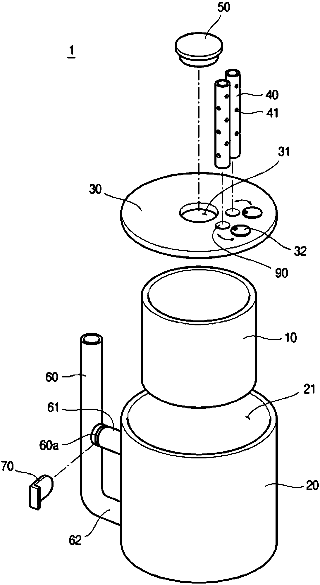
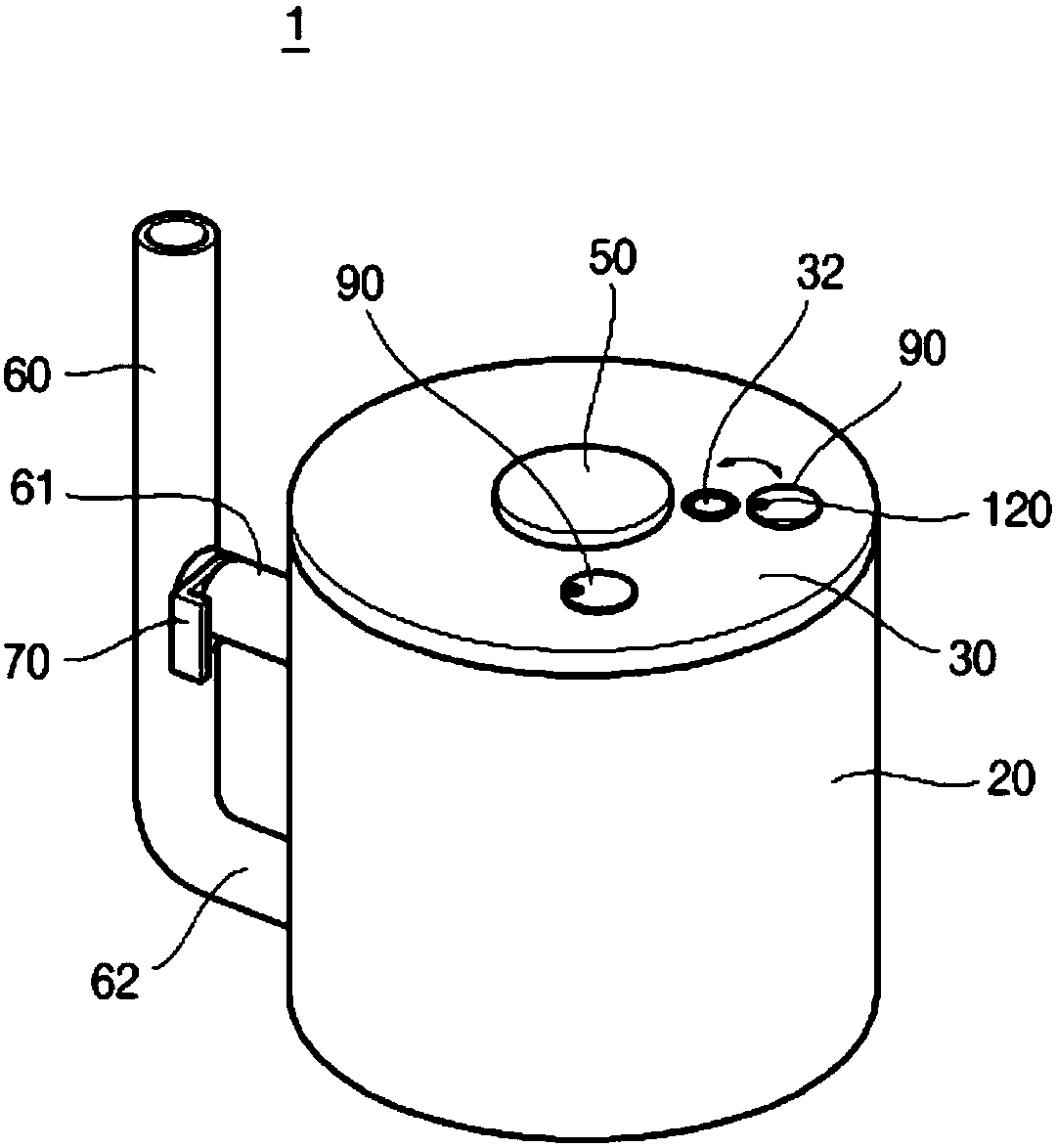
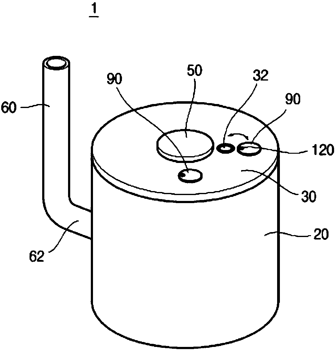
[0062] Hereinafter, the present invention will be described in detail with reference to the drawings.

[0063] figure 1 To show an exploded perspective view of the stove of the present invention, figure 2 To show the combined perspective view of the stove of the present invention, image 3 In order to show a combined perspective view of an embodiment of the chimney applied to the stove of the present invention, Figure 4 To show a plan view of a state where the main body of the furnace applied to the present invention is inserted into the heating unit in an eccentric state, Figure 5 To show a cross-sectional view of the state in which the auxiliary combustion tube is applied to the furnace of the present invention, Image 6 To show a cross-sectional view of the state in which the auxiliary combustion tube and the auxiliary gas supply unit are applied to the furnace of the present invention, Figure 7 In order to show a cross-sectional view of the auxiliary input unit applied to th...


PUM


Abstract

The present invention relates to a stove, and the objective of the present invention is to facilitate assembly through a simplified structure, improve combustion efficiency, enable heat loss to be minimized through a heating method using indirect heating, and enable a combustion chamber to be maintained at a high temperature at all times. The stove according to the present invention comprises: a main body having the combustion chamber, in which a material to be combusted is combusted, formed therein; a heating part in which the main body is accommodated and radiating combustion heat in the combustion chamber to the outside; a lid part for closing an opening formed at the heating part, and opening and closing, by a plug, an input hole, which is formed at one side thereof, for allowing the material to be combusted to be put into the combustion chamber therethrough; and air supply pipes provided at the lid part, and accommodated in the combustion chamber so as to supply heated external air to the combustion chamber, thereby enhancing the combustion of the material to be combusted.

Description

Technical field [0001] The invention relates to a stove. Background technique [0002] Generally speaking, stoves are widely used as one of heating mechanisms for heating indoors, ranging from large industrial stoves such as agriculture and animal husbandry to small stoves that can be used for outdoor living such as camping. [0003] In order to realize high-efficiency heating, the existing stove basically realizes centralized ignition and installation of chimneys, but does not realize the heat insulation of the fire chamber. [0004] For the above-mentioned heat insulation, of course, refractory bricks or heat insulating bricks are installed inside the furnace, or reinforced with heat insulation materials such as perlite, partition treatment is also performed, and hot gas delay plates and heat storage structures are added. However, in this case, there is a problem that the initial ignition of the burned material is not achieved, and the furnace manufacturing time, manufacturing cos...

Claims


Application Information

Patent Timeline
Patent Type & Authority Patents(China)
IPC IPC(8): F24B1/00
CPCF24B1/189F24B1/19F24B1/192F24B1/195F24B5/02F24B7/02
Inventor 李承逸
Owner 李承逸
Why Eureka
Try Eureka