
Underground continuous wall seepage detection device based on distributed optical fiber temperature measurement

An underground diaphragm wall and distributed optical fiber technology, which is used in measuring devices, thermometers, and heat measurement, etc., can solve the problems of undisclosed and inability to detect the underground diaphragm wall, and the construction process of the underground diaphragm wall and the dam is different, so as to simplify the process, Cost savings, guaranteed sensitivity

Active Publication Date: 2018-02-23
TONGJI UNIV
View PDF6 Cites 10 Cited by
  • Summary
  • Abstract
  • Description
  • Claims
  • Application Information

AI Technical Summary

Problems solved by technology

Optical fiber sensing technology has been disclosed in the patent literature for the monitoring method of oil and gas pipeline leakage and the device for monitoring the leakage of dams, but a device and method for detecting leakage of underground diaphragm walls has not been disclosed so far, and the steel bars of underground diaphragm walls The detection of leakage in concrete structures is different from that of dams, embankments, rock-soil walls, etc., and the construction techniques of underground diaphragm walls and structures such as embankments are also different, so the devices and methods for monitoring leakage of embankments cannot be directly used for Detecting leaks in underground diaphragm walls

Method used


Image

  • Underground continuous wall seepage detection device based on distributed optical fiber temperature measurement

Examples


Embodiment Construction

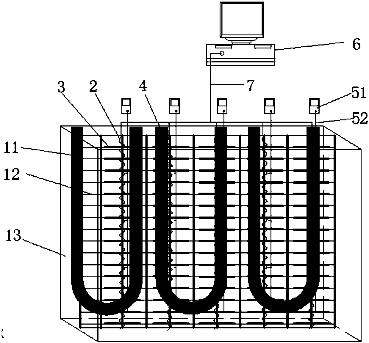
[0020] The technical solution of the underground diaphragm wall leakage detection device based on distributed optical fiber temperature measurement provided by the present invention will be further described below in conjunction with specific embodiments and accompanying drawings. The advantages and features of the present invention will become clearer in conjunction with the following description.

[0021] It should be noted that the embodiments of the present invention have better implementability and are not intended to limit the present invention in any form. The technical features or combinations of technical features described in the embodiments of the present invention should not be regarded as isolated, and they can be combined with each other to achieve better technical effects. The scope of the preferred embodiment of the present invention may also include other implementations, and this should be understood by those skilled in the art to which the embodiments of the...


PUM


Abstract

The invention provides an underground continuous wall seepage detection device based on distributed optical fiber temperature measurement, which relates to the field of geotechnical engineering fielddetection and safety protection. The underground continuous wall seepage detection device comprises a heating system, a temperature measurement system and a data processing and analysis system. The heating system is used for heating a soil body behind an underground continuous wall, so that a temperature difference exists between seepage water and optical fibers. The temperature measurement systemis used for measuring an initial temperature value of the optical fibers and a temperature field in the underground continuous wall after heating the soil body. The data processing and analysis system is used for processing temperature data, acquiring a place where the seepage occurs and acquiring a seepage rate of the seepage place. The underground continuous wall seepage detection device makesfull use of a steel reinforcement cage of the underground continuous wall to lay the optical fibers and thermal conductive wires, so that the longitudinal optical fibers and the transverse thermal conductive wires form net-like distributed optical fibers, and the cost is saved. The underground continuous wall seepage detection device further uses the heating system to heat the seepage water, magnifies the temperature difference of the seepage region, does not need to perform surface treatment on the optical fibers, ensures the sensitivity of the optical fibers, and simplifies the process.

Description

technical field [0001] The invention belongs to the field of geotechnical engineering site detection and safety protection equipment, and in particular relates to a device for leak detection of an underground continuous wall. Background technique [0002] In recent years, with the gradual increase of high-rise buildings in our country, the requirements of buildings for foundation pits are also getting higher and higher. The leakage of underground diaphragm walls in foundation pit engineering is an important factor affecting project safety. Learn from reliable detection technology in time Its leakage location and leakage degree have attracted more and more attention and attention in the engineering field. At present, the methods used for leak detection include electrical detection, capacitive sensors, etc., but these methods have their limitations and cannot be well applied to the leak detection of underground diaphragm walls. Distributed optical fiber temperature sensing te...

Claims


Application Information

Patent Timeline
IPC IPC(8): G01K11/32G01N15/08G01N25/72G01K11/324
CPCG01K11/3206G01N15/082G01N25/72
Inventor 王建秀赵宇刘笑天崔韬徐娜顾其伟张宇澄
Owner TONGJI UNIV
Learn More