Monitoring device and method for aerosol in pipeline and pipeline system

A monitoring device and aerosol technology, applied in the field of pipelines, can solve the problems of high requirements on technology and equipment, increase of site construction workload, comprehensive cost of equipment space, etc., and increase of gas leakage risk points, etc., so as to improve accuracy, The effect of avoiding waste and avoiding data errors

Active Publication Date: 2018-02-23
CHINA UNIV OF PETROLEUM (BEIJING)
View PDF21 Cites 14 Cited by
  • Summary
  • Abstract
  • Description
  • Claims
  • Application Information

AI Technical Summary

Problems solved by technology

It can also be understood as "the sample gas is passed into other containers to avoid emptying and wasting" or "pressurized and reinjected into the original pipeline". There are many risk points of gas leakage, such as machine and connecting pipeline, which also increases the comprehensive cost of purchasing sample gas pressurization and reinjection equipment, on-site construction workload, and equipment space.
[0008] 2. The electrostatic concentration sensor used in this invention can only roughly obtain the concentration of particulate matter impurities, and cannot simultaneously realize the online testing of the concentration and particle size distribution of particulate matter impurities, especially not suitable for online monitoring and analysis of filtration and separation equipment for different particle sizes The separation efficiency of the particles

Method used


Image

  • Monitoring device and method for aerosol in pipeline and pipeline system
  • Monitoring device and method for aerosol in pipeline and pipeline system
  • Monitoring device and method for aerosol in pipeline and pipeline system

Examples


Embodiment Construction

[0054] The following will clearly and completely describe the technical solutions in the embodiments of the present invention with reference to the accompanying drawings in the embodiments of the present invention. Obviously, the described embodiments are only some, not all, embodiments of the present invention. Based on the embodiments of the present invention, all other embodiments obtained by persons of ordinary skill in the art without making creative efforts belong to the protection scope of the present invention.

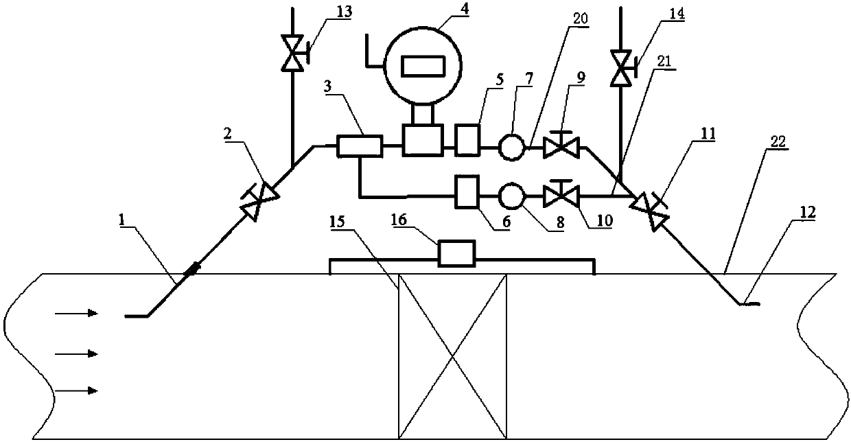
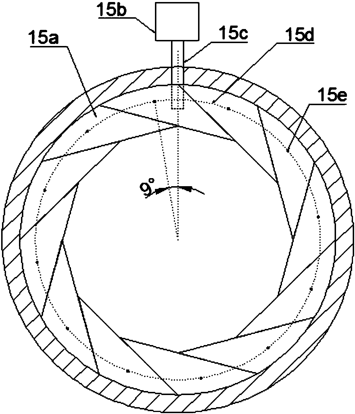
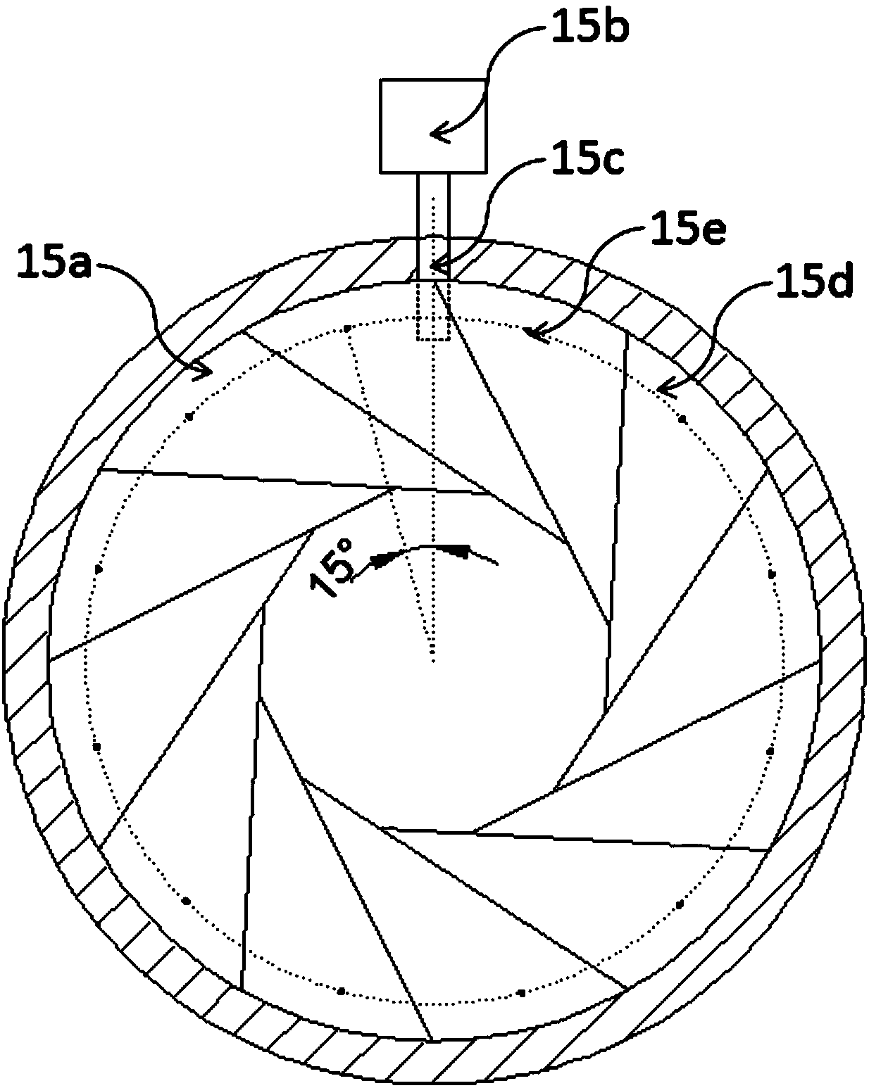
[0055] refer to figure 1 As shown, the embodiment of the present application discloses an aerosol monitoring device 17 in a pipeline, including: a diameter-changing mechanism 15, which can control the opening of the pipeline 22; a detection path 20, the The detection path 20 is provided with a measuring device for testing the aerosol concentration and particle size distribution; a sampling mechanism, the inlet port of the sampling mechanism communicates with t...


PUM


Abstract

The invention discloses a monitoring device and method for aerosol in a pipeline and a pipeline system. The monitoring device comprises a variable diameter mechanism, a detection circuit, a sampling mechanism, a backflow mechanism, a first detection mechanism, a second detection mechanism and a first control valve, wherein the variable diameter mechanism can control the opening of the pipeline; the detection circuit is provided with a measuring device for testing the aerosol concentration and the particle size distribution; the inlet end of the sampling mechanism is communicated with the pipeline positioned at the upstream of the variable diameter mechanism, and the outlet end of the sampling mechanism is communicated with an inlet of the detection circuit; the outlet end of the backflow mechanism is communicated with the pipeline positioned at the downstream of the variable diameter mechanism, and the inlet end of the backflow mechanism is communicated with an outlet of the detectioncircuit; the first detection mechanism is used for detecting the flow rate of gas in the pipeline; the second detection mechanism is used for detecting the flow rate of gas in the detection circuit; and the first control valve is used for controlling the flow rate of the gas in the detection circuit. The monitoring device disclosed by the invention has the benefit that the opening of the variablediameter mechanism can be dynamically adjusted, so that the flow rate of sample gas is the same as that of the gas in the pipeline, and the measuring accuracy is improved.

Description

technical field [0001] The invention relates to the pipeline field, in particular to an aerosol monitoring device and method in a pipeline and a pipeline system. Background technique [0002] Generally, the gas in the pipeline often contains some dust or impurities, which may endanger the operation safety of the pipeline. For example, high-pressure natural gas pipelines generally contain particulate impurities such as dust and liquid droplets during the mining and gathering process. Especially for newly built high-pressure natural gas pipelines, the dust left over from construction directly threatens the operation safety of downstream equipment, especially the impact on gas turbines and compressors. During the long-term operation of high-pressure natural gas pipelines, due to the change of natural gas quality, there will be the formation and deposition of condensate and water, and the internal corrosion and inner coating peeling off of high-pressure natural gas pipelines wi...

Claims


Application Information

Patent Timeline
Patent Type & Authority Applications(China)
IPC IPC(8): G01N15/02G01N15/06G01N33/00
CPCG01N15/0205G01N15/06G01N33/00G01N2015/0693Y02E30/30
Inventor 刘震姬忠礼吴小林卢利锋许乔奇宋暄
Owner CHINA UNIV OF PETROLEUM (BEIJING)
Why Eureka
Try Eureka