Positioning method of scanning sampling starting point

A positioning method and starting point technology, which are used in measuring devices, material analysis by optical means, instruments, etc., can solve the problems of scanning imaging starting point drift, etc., and achieve the effect of improving accuracy, improving accuracy and accurate positioning.

Inactive Publication Date: 2018-02-23
ANHUI ZHONGKE OPTIC ELECTRONICS COLOR SORTER MACHINERY
View PDF6 Cites 2 Cited by
  • Summary
  • Abstract
  • Description
  • Claims
  • Application Information

AI Technical Summary

Problems solved by technology

[0007] In order to solve the drift problem existing in the actual engineering application of the existing scanning imaging starting point, the present invention provides an accurate positioning method to overcome the drifting of the scanning sampling starting point

Method used


Image

  • Positioning method of scanning sampling starting point
  • Positioning method of scanning sampling starting point
  • Positioning method of scanning sampling starting point

Examples


Embodiment 1

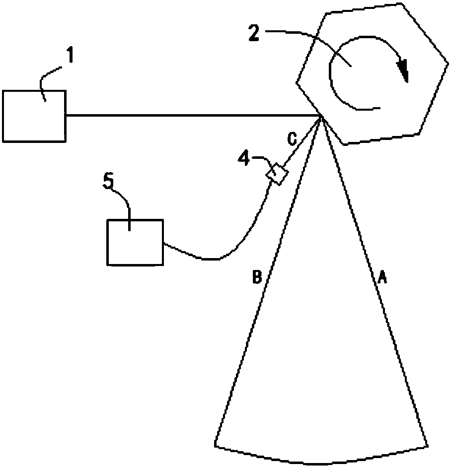
[0025] see figure 1 , a method for positioning a scanning sampling starting point, comprising the following steps:

[0026] First, the light source 1 is set opposite to the scanning mirror 2. The light source 1 is not limited to a laser light source, and can also be any collimated light source, such as LED, halogen lamp; The scanning mirror 2 forms the light scanning area A-C from the outside to the inside, where the area covered by light A to light B is within the effective range of optical scanning, and the area between light B to light C is within the effective range of optical scanning outside the area;

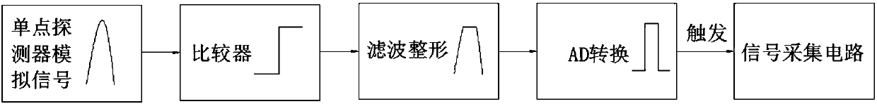
[0027] Single-point detector 4 is set on the position of light C inside the light scanning area, and described single-point detector 4 is photodiode, avalanche diode or photomultiplier tube; reflected light signal; see figure 2 , a comparator is connected to the output terminal of the single-point detector 4, and the comparator discriminates signals exceeding the ampl...

Embodiment 2

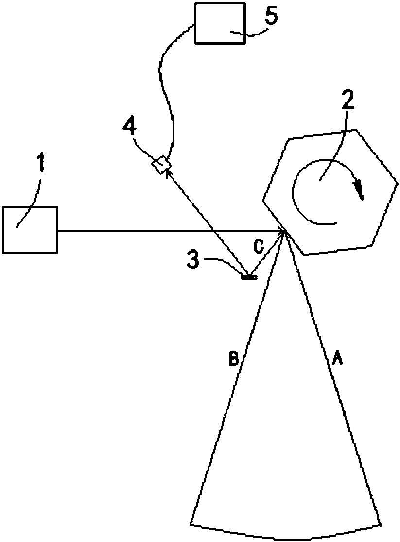
[0031] see image 3 , the refraction member 3 is set at the position of the light C of the scanning mirror 2, the refraction member 3 is a coated mirror, a metal polished mirror surface or a film surface; the refraction member 3 reflects the light C, and the single point detector 4 is arranged on the refraction member 3 On the position of the reflected light of light C; the rest are the same as in Embodiment 1.

[0032] During work, each frame of image will have an analog signal generated by a single-point detector 7. After the comparator discriminates the signal exceeding the amplitude h1, the noise filtering of the filter and the conversion of the signal by the AD converter, the signal The sampling of the acquisition circuit is accurate, and the critical reflection at the light C of the scanning mirror is always collected, so as to ensure that the images collected in each frame can be effectively spliced, improve the accuracy of photoelectric recognition, and make the positi...


PUM


Abstract

The invention discloses a positioning method of a scanning sampling starting point. The method comprises arranging a light source and a scanning mirror opposite to the light source, perpendicularly emitting lights emitted by the light source to the scanning mirror, rotating the scanning mirror so that an A-C light scanning zone from outside to inside is formed below the scanning mirror, arranginga single point detector at the inner side of the light scanning zone, detecting and acquiring light C of the scanning mirror through the single point detector, converting a light signal into an electric signal and outputting an image information collection triggering signal through an output end of the single point detector. The positioning method ensures effective joining of images acquired by each frame, improves the photoelectric recognition precision, realizes more accurate scanning imaging starting point positioning, prevents the occurrence of the starting point drift in the existing practical projects and further improves the accuracy of image acquisition.

Description

technical field [0001] This patent belongs to the technical field of industrial imaging, and in particular relates to a method for positioning the starting point of scanning imaging sampling. Background technique [0002] In the past few years, CCD imaging technology has made great progress in the field of photoelectric recognition of visible light, but it also faces some limitations. For detection, the signal strength is too weak and the signal-to-noise ratio is obviously low. At this time, it is necessary to use a special high-sensitivity detector as a photoelectric detection device, and combine it with a scanning device to realize imaging. [0003] During scanning and imaging, affected by the stability of scanning components, the angular velocity is not completely uniform throughout the rotation process, and there is a certain deviation. The sampling start point can be accurately determined within a period of time by using software or hardware timing, but Long-term opera...

Claims


Application Information

Patent Timeline
Patent Type & Authority Applications(China)
IPC IPC(8): G01N21/17
Inventor 方杰贾星明孙敏桂岳疏义桂
Owner ANHUI ZHONGKE OPTIC ELECTRONICS COLOR SORTER MACHINERY
Why Eureka
Try Eureka