Exposure illumination device

A technology for lighting devices and exposure surfaces, which is applied in photolithographic exposure devices, microlithography exposure equipment, optics, etc., can solve the problems of increasing substrate manufacturing costs, increasing costs, and increasing replacement frequency, achieving stable substrate exposure and improving Effects of manufacturing efficiency, securing uniformity, and sufficient illuminance

Active Publication Date: 2018-02-23
YOKOHAMA LEADING DESIGN
View PDF10 Cites 1 Cited by
  • Summary
  • Abstract
  • Description
  • Claims
  • Application Information

AI Technical Summary

Problems solved by technology

[0003] However, UV lamps or halogen lamps used for exposure lighting can achieve high brightness, but generally have a short life
Theref

Method used


Image

  • Exposure illumination device
  • Exposure illumination device
  • Exposure illumination device

Examples


no. 1 Embodiment approach

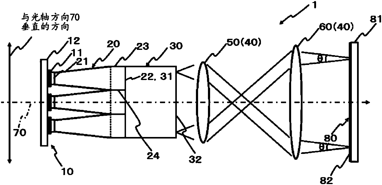
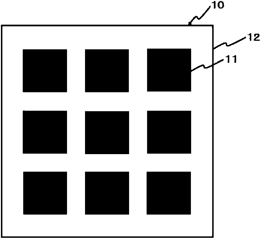
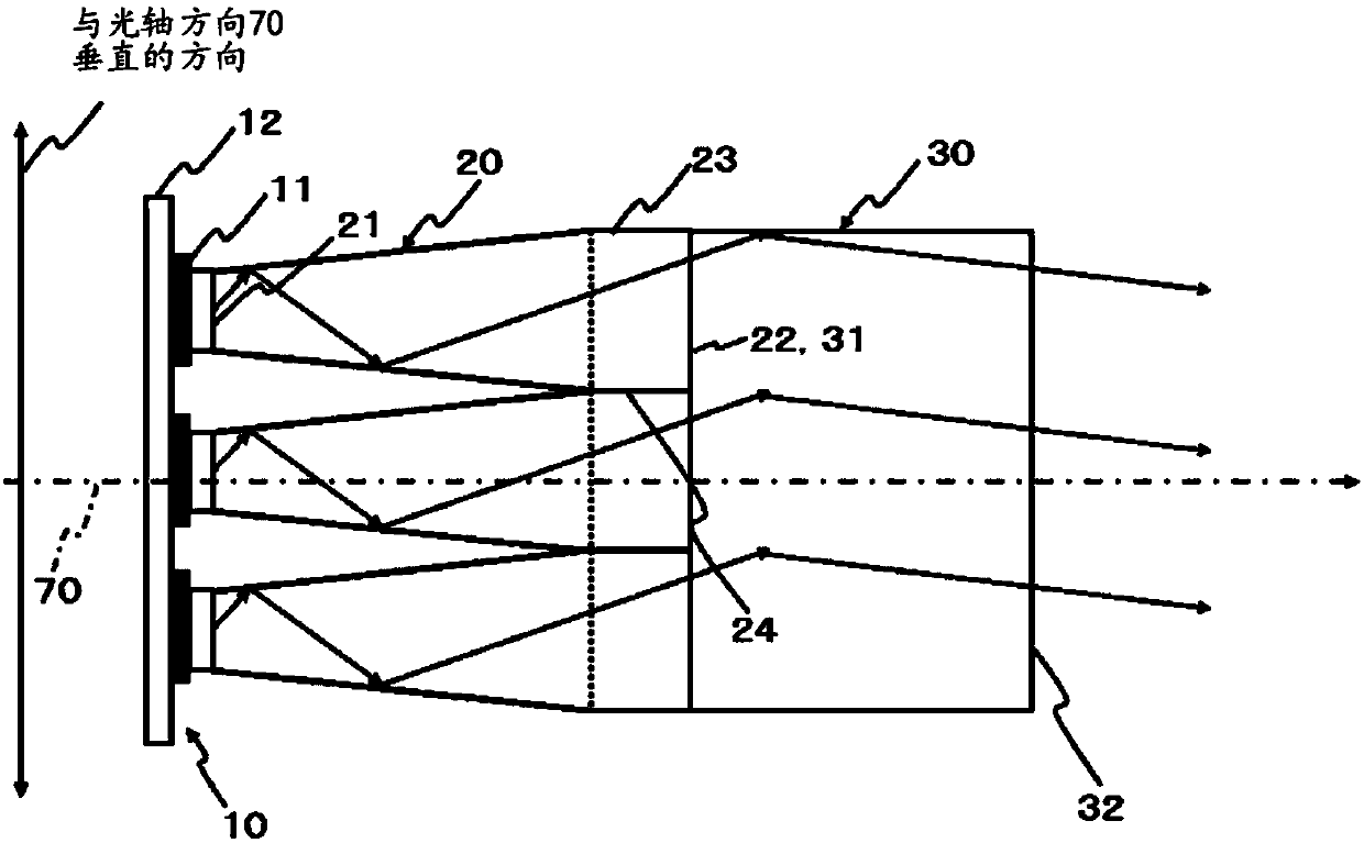
[0087] refer to Figure 1 to Figure 4 , the first embodiment of the present invention will be described in detail. figure 1 is a configuration diagram showing an outline of the overall configuration of the exposure lighting device according to the first embodiment of the present invention, figure 2 It is a front view showing the overall configuration of the light source in the exposure lighting device, image 3 It is a figure for explaining the technical effect of 1st Embodiment, Figure 4 is another diagram for explaining the technical effect of the first embodiment, Figure 4 The oblique line in □ indicates that a large surface light source is formed on the output end surface 22 of the first light guide 20 and the light beam is output.

[0088] refer to figure 1 The outline of the exposure lighting device of the present invention will be described. The exposure lighting device 1 has a light source 10, a first light guide body 20, a second light guide body 30, and an ...

no. 2 Embodiment approach

[0101] Next, refer to Figure 5 , the second embodiment of the present invention will be described in detail. In the description of the second embodiment, the configurations assigned the same reference numerals as those in the first embodiment described above will be regarded as the same configurations, and their descriptions will be omitted.

[0102] An example in which the position of the second light guide is changed is shown for the exposure lighting device 2 of the second embodiment. That is to say, in the second embodiment, the optical member 400 is provided between the first light guide 20 and the second light guide 200, and the second light guide 200 is refracted by the optical member 400 and converged from the first light guide. The light beam emitted by the light body 20 is used to reduce the light beam and make it incident.

[0103]Similar to the first embodiment described above, the second light guide 200 is a rod. More specifically, the second light guide 200 i...

no. 3 Embodiment approach

[0108] Next, refer to Figure 6 , the third embodiment of the present invention will be described in detail. In the description of the third embodiment, the configurations assigned the same reference numerals as those in the first embodiment and the second embodiment described above will be regarded as the same configurations and their description will be omitted.

[0109] The example which changed the structure of the 2nd light guide in 2nd Embodiment is shown about the exposure illumination apparatus 3 of this 3rd Embodiment. That is, in the third embodiment, the second light guide 300 is a compound eye and is formed of synthetic quartz or the like. More specifically, in the second light guide 300, a first compound eye 301a formed by a plurality of lenses 301b is provided on the incident end surface 301 side, and a second compound eye 302a formed by a plurality of lenses 302b is provided on the exit end surface 302 side. The optical device is configured to refract and conv...


PUM


Abstract

An exposure illumination device provided by the present invention irradiate the light beams emitted out by the light sources 10 of a plurality of LED assemblies which are in discrete configuration according to the specified intervals to an exposure surface 80, a plurality of tapered first light guide bodies 20 are arranged at the emergent side of each of the plurality of LED assemblies, along theoptical axis direction 70 of the light beams emitted out by the LED assemblies 11, the sizes of the plurality of tapered first light guide bodies 20 increase gradually, and the area of the emergent end faces 22 is set to be greater than the area of the incident end faces 21 of the light beams, and the size of the light beam emitted out from the LED assembly 11 on the incident end face 21 of the first light guide body is set to be greater than the incident end face 21 of the first light guide body. The exposure illumination device can guarantee the brightness distribution uniformity of the light beams emitted out from the plurality of LED assemblies which are in discrete configuration according to the specified intervals and the sufficient illumination, and carry out the stable substrate exposure.

Description

technical field [0001] The present invention relates to an exposure lighting device, and more particularly to an exposure lighting device that irradiates an exposure surface with light beams emitted from a plurality of LED modules discretely arranged at intervals. Background technique [0002] Conventionally, various exposure lighting devices for exposing a substrate are known. The exposure lighting device irradiates the light beam emitted from the light source to the exposure surface through optical equipment such as a lens system, and exposes the substrate. As a light source for such an exposure lighting device, a light source with high brightness is selected. As shown in Patent Document 1 and Patent Document 2, conventionally, for example, an ultraviolet lamp or a halogen lamp has been used. [0003] However, ultraviolet lamps or halogen lamps used in exposure lighting devices generally have a short life, although high brightness can be obtained. Therefore, an increase...

Claims


Application Information

Patent Timeline
IPC IPC(8): G03F7/20
CPCG03F7/7005G03F7/70075G03F7/7015
Inventor 末永丰
Owner YOKOHAMA LEADING DESIGN
Why Eureka
Try Eureka