Microfluidic photoionization detector

A ionization detector and microfluidic technology, applied in the field of microfluidic photoionization detectors, can solve the problems of PID involvement, slow response time, limiting the use and integration of PID, etc.

Active Publication Date: 2018-02-23
RGT UNIV OF MICHIGAN
View PDF4 Cites 4 Cited by
  • Summary
  • Abstract
  • Description
  • Claims
  • Application Information

AI Technical Summary

Problems solved by technology

However, PIDs suffer from slow response times due to large ionization chambers and dead volumes, thus limiting the use and integration of PIDs in GC systems

Method used


Image

  • Microfluidic photoionization detector
  • Microfluidic photoionization detector
  • Microfluidic photoionization detector

Examples


Embodiment Construction

[0041] Example embodiments will now be described more fully with reference to the accompanying drawings.

[0042] Example embodiments are provided so that this disclosure will be thorough, and will fully convey the scope to those who are skilled in the art. Numerous specific details are set forth such as examples of specific compositions, components, devices, and methods, in order to provide a thorough understanding of embodiments of the present disclosure. It will be apparent to those skilled in the art that specific details need not be employed, that example embodiments may be embodied in many different forms and that neither should be construed to limit the scope of the disclosure. In some example embodiments, well-known processes, well-known device structures, and well-known technologies are not described in detail.

[0043] The terminology used herein is for the purpose of describing particular example embodiments only and is not intended to be limiting. As used herein,...


PUM


Abstract

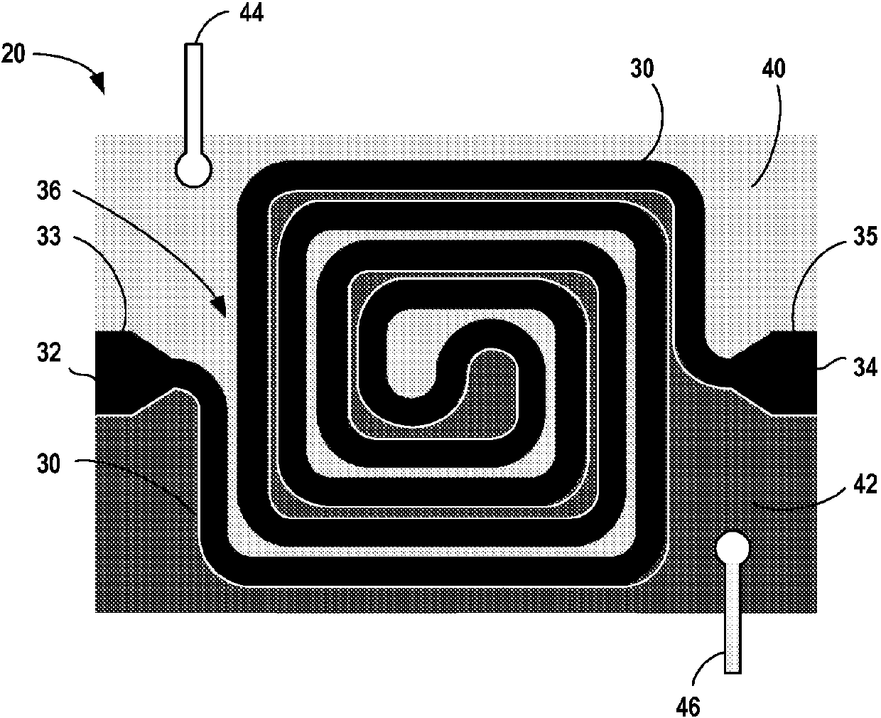
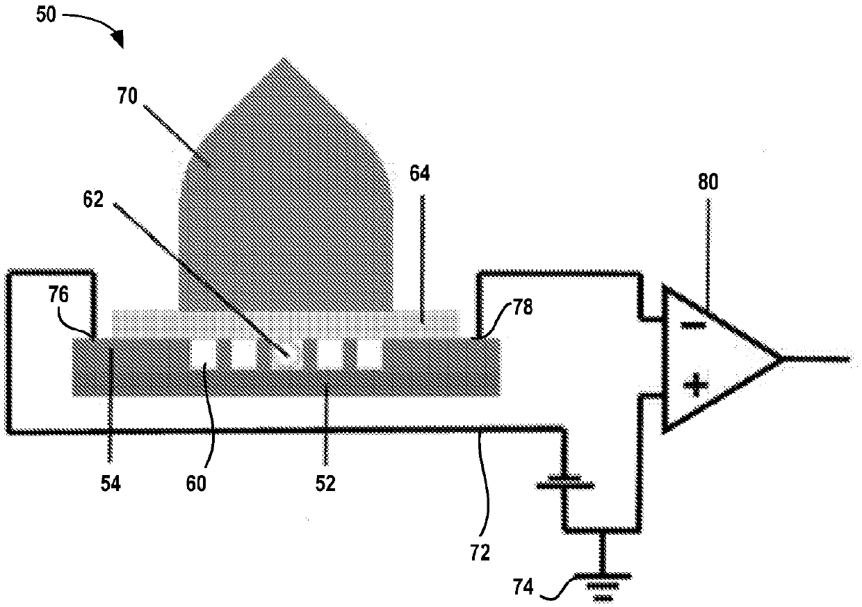
A rapid flow-through, highly sensitive microfluidic photoionization detector (PID) which is micro-fabricated directly onto a substrate, such as a conductive silicon wafer, is provided. The microfluidic PID has an ionization chamber volume of less than 9 [mu]L. The microfluidic PID may have a flow through design with a microfluidic channel defines a serpentine pattern on the substrate. The flow through design of the microfluidic PID results in negligible dead volume, thus allowing a shortened response time over existing commercially available designs. Such microfluidic PIDs are particularly useful with gas chromatography (GC), including microGC and multidimensional microGC systems. Methods for calibrating PIDs are also provided.

Description

[0001] Cross References to Related Applications [0002] This application claims the benefit of U.S. Provisional Application No. 62 / 157,238, filed May 5, 2015. The entire disclosure of the above application is incorporated herein by reference. [0003] government rights [0004] This invention was made with government support under IIP-1342917 awarded by the National Science Foundation and 83564401 awarded by the Environmental Protection Agency. The government has certain rights in this invention. technical field [0005] The invention relates to a high-sensitivity microfluidic photoionization detector, which can be used for target analyte detection and analysis together with gas chromatography. Background technique [0006] Gas chromatography (GC) is widely used for the analysis of volatile organic compounds (VOCs) as well as other analyte compounds. When used for analysis, GC systems also typically include an analyte detector. A flame ionization detector (FID) is a va...

Claims


Application Information

Patent Timeline
IPC IPC(8): G01N30/74
CPCG01N30/74G01N27/66G01N2030/642G01N30/6095G01N30/64G01N27/68
Inventor 范旭东朱洪波罗伯特·尼代茨樱林胜雄周孟连李志原
Owner RGT UNIV OF MICHIGAN
Why Eureka
Try Eureka