Emergency air spring assembly

A technology of air springs and components, which is applied in the direction of springs, shock absorbers-spring combinations, springs/shock absorbers, etc., can solve problems such as inability to meet stiffness requirements and soft stop requirements, so as to improve dynamic displacement capacity and reduce abnormal Linear, Simple Effects

Pending Publication Date: 2018-02-27
ZHUZHOU TIMES NEW MATERIALS TECH
View PDF8 Cites 4 Cited by
  • Summary
  • Abstract
  • Description
  • Claims
  • Application Information

AI Technical Summary

Problems solved by technology

Therefore the existing rubber emergency spring cannot meet this requirement
[0003] When the air spring is deflated, there will generally be a hard stop in the vertical direction, and at the same time there will be later

Method used


Image

  • Emergency air spring assembly

Examples


Example Embodiment

[0021] The present invention will be further described in detail below with reference to the drawings and specific embodiments of the specification.

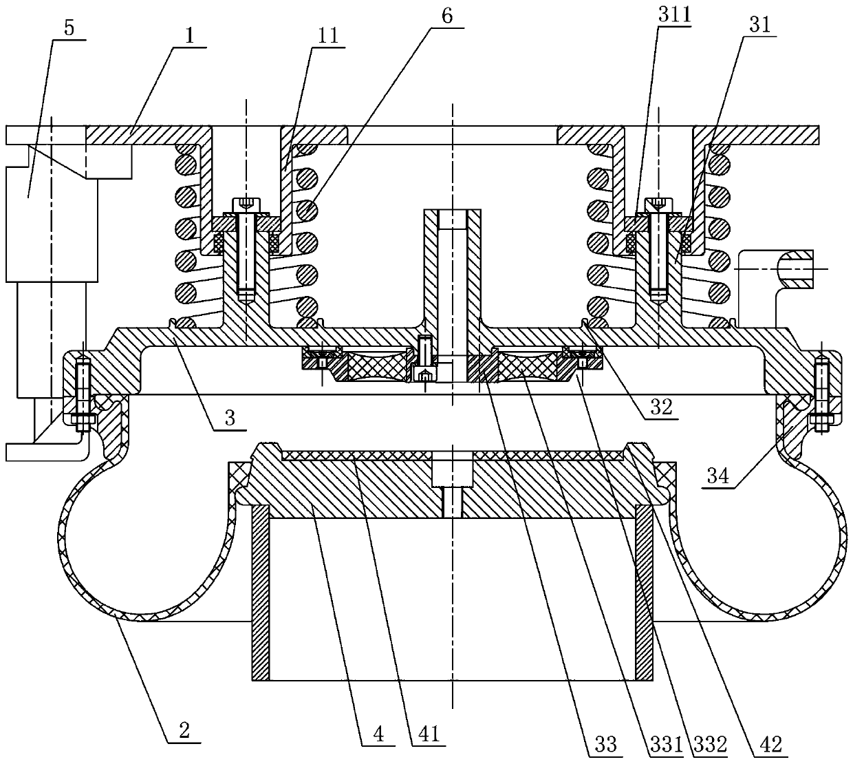
[0022] Such as figure 1 As shown, an embodiment of the emergency air spring assembly of the present invention includes an upper cover plate 1, an air bag 2, an upper end plate 3, and a lower end plate 4. The outer circumference of the upper end plate 3 is connected to the outer circumference of the lower end plate 4 through the air bag 2, and the upper cover A plurality of steel springs 6 are pressed between the plate 1 and the upper end plate 3 along the circumferential direction, and a damper 5 is also installed between the upper cover plate 1 and the upper end plate 3. In this structure, a parallel structure is formed by arranging a plurality of steel springs 6 and dampers 5 in the circumferential direction. The structure is simple and easy to install. Moreover, the vertical stiffness is all provided by the steel springs 6, and ...


PUM


Abstract

The invention discloses an emergency air spring assembly. The emergency air spring assembly comprises an upper cover plate, air bags, an upper end plate and a lower end plate; the periphery of the upper end plate is connected with the periphery of the lower end plate through the air bags; a plurality of steel springs are arranged between the upper cover plate and the lower end plate in the peripheral direction; and a damper is also mounted between the upper cover plate and the upper end plate. The emergency air spring assembly has the advantages of simple structure, convenience in mounting, low overload vertical stiffness, large vertical deformation, high comfortableness and stability, and capacity of preventing creepage and realizing soft stop.

Description

technical field [0001] The invention mainly relates to shock absorbing technology, in particular to an emergency air spring assembly. Background technique [0002] Air spring components are used in a wide range of applications, such as railway carriages, heavy-duty vehicles, and other applications where cushioning or shock absorption is important. Typically, such spring assemblies include an elastomeric body positioned between a pair of rigid end plates. The elastomer is made of rubber and is compressed by the load applied to the spring assembly. In the prior art, the rubber emergency spring will creep during the service life due to the characteristics of the rubber, and at the same time, due to the nonlinearity of the rubber, the vertical stiffness will increase when the load increases. In some high-speed train projects, the emergency spring is required to have a small change in vertical stiffness, a large dynamic displacement, and no padding is allowed during the service...

Claims


Application Information

Patent Timeline
IPC IPC(8): F16F13/00F16F9/04
Inventor 叶特农多敏陈灿辉程海涛周军陈强陈文海金状兵彭旋
Owner ZHUZHOU TIMES NEW MATERIALS TECH
Why Eureka
Try Eureka