Charge pump circuit with enhanced drive capability

A charge pump and capacitor technology, applied in the direction of conversion equipment without intermediate conversion to AC, can solve the problems of large output drive capability, uneven capacitance distribution, and charge pump circuit can not be realized, and achieve the effect of improving output drive capability

Active Publication Date: 2019-12-03
PEKING UNIV SHENZHEN GRADUATE SCHOOL
View PDF6 Cites 0 Cited by
  • Summary
  • Abstract
  • Description
  • Claims
  • Application Information

AI Technical Summary

Problems solved by technology

Although this solution effectively utilizes all the on-chip capacitors and can improve the load capacity, the output drive capability of the charge pump also needs to be improved.
This is because the capacitance distribution of the combined charge pump units is uneven, so the charge pump circuit cannot achieve the maximum output drive capability

Method used


Image

  • Charge pump circuit with enhanced drive capability
  • Charge pump circuit with enhanced drive capability
  • Charge pump circuit with enhanced drive capability

Examples


Embodiment Construction

[0029] Exemplary embodiments of the present application will be described in detail below with reference to the accompanying drawings. It should be noted that the relative arrangements of components and steps, numerical expressions and numerical values ​​set forth in these embodiments do not limit the scope of the present application unless specifically stated otherwise.

[0030] The following description of at least one exemplary embodiment is merely illustrative in nature and not intended as any limitation of the application, its application or uses.

[0031] Techniques, methods and devices known to those of ordinary skill in the relevant art may not be discussed in detail, but where appropriate, such techniques, methods and devices should be considered part of the description.

[0032] In all examples shown and discussed herein, any specific values ​​should be construed as exemplary only, and not as limitations. Therefore, other instances of the exemplary embodiment may ha...


PUM


Abstract

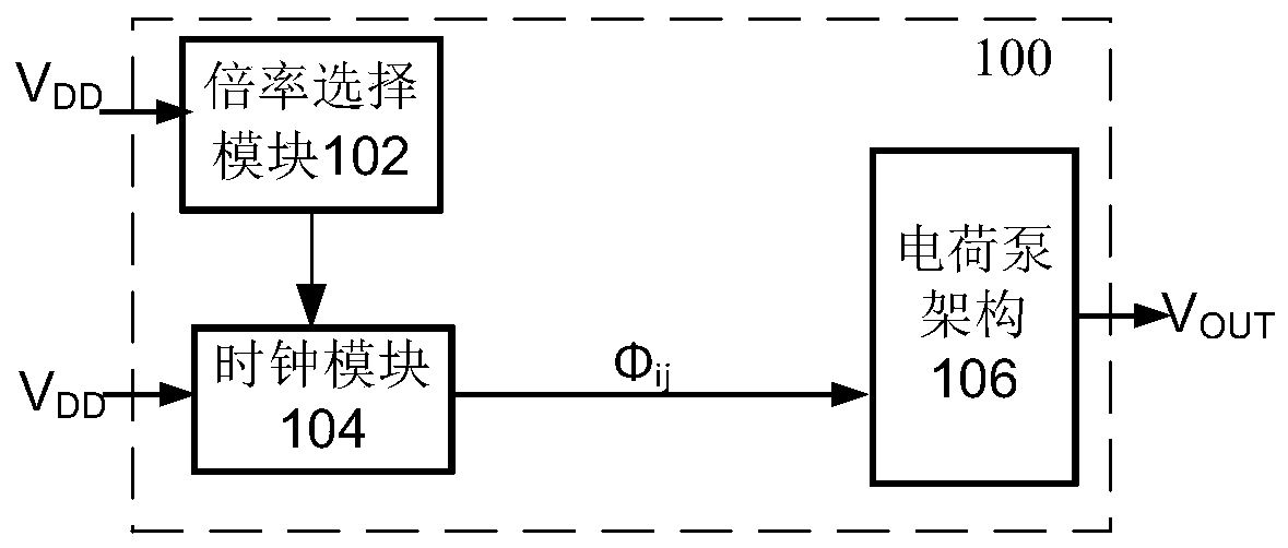
The invention provides a charge pump which comprises a charge pump main module. The charge pump main module comprises X first-stage charge pump units, a clock module and a multiplying power selectionmodule, wherein X is a positive integer larger than 1, the clock module is used for outputting a clock sequence for adjusting the coupling relationship between the first-stage charge pump units, and the coupling relationship inside the first-stage charge pump units; the multiplying power selection module controls the clock module to output a corresponding clock sequence according to the needed output multiplying power; the charge pump main module regroups the X first-stage charge pump units into Y second-stage charge pump units according to the received clock sequence, Y is a positive integerlarger than or equal to 1 but smaller than or equal to X, the Y second-stage charge pump units have the same equivalent capacitance for each integer multiplying power of the reciprocal of the integermultiplying power or the number difference of the first-stage charge pump units included in each second-stage charge pump unit is smaller than or equal to 1. The invention further provides a method adopting charge pumps to adjust voltage.

Description

technical field [0001] The application relates to the field of integrated circuits, in particular to a full rate charge pump with high output driving capability. Background technique [0002] The charge pump structure is widely used in the power management system design of display screens or handheld devices. A charge pump, also known as a switched capacitor voltage converter, is a type of DC converter that uses capacitors instead of inductors or transformers to store energy. The input voltage can be raised or lowered by a charge pump, and can even be used to generate negative voltages. The charge pump structure uses a switch array to control the charging and discharging of capacitors in a certain way, so that the input voltage is multiplied or subtracted by a certain factor, so as to obtain the required output voltage. Since the (capacitive) charge pump does not include an inductor, electromagnetic interference caused by the inductor can be avoided. [0003] Regardless o...

Claims


Application Information

Patent Timeline
Patent Type & Authority Patents(China)
IPC IPC(8): H02M3/07
CPCH02M3/07
Inventor 张敏林和生刘宾杰张硕
Owner PEKING UNIV SHENZHEN GRADUATE SCHOOL
Why Eureka
Try Eureka