
A radiation-resistant ultra-high-speed trigger circuit and aerospace ultra-high-speed trigger

A trigger circuit, ultra-high-speed technology, applied in the direction of electric pulse generator circuit, etc., can solve the problems of performance limitation, single event flipping interference, etc., achieve the effect of fast speed, enhanced output driving ability, and reduced transmission delay

Active Publication Date: 2017-11-17
SHENZHEN STATE MICROELECTRONICS CO LTD
View PDF3 Cites 0 Cited by
  • Summary
  • Abstract
  • Description
  • Claims
  • Application Information

AI Technical Summary

Problems solved by technology

[0005] The purpose of the embodiments of the present invention is to provide an anti-irradiation ultra-high-speed trigger circuit, which aims to solve the problems of limited performance and susceptibility to single-event upset interference when traditional triggers are used in aerospace environments

Method used


Image

  • A radiation-resistant ultra-high-speed trigger circuit and aerospace ultra-high-speed trigger
  • A radiation-resistant ultra-high-speed trigger circuit and aerospace ultra-high-speed trigger
  • A radiation-resistant ultra-high-speed trigger circuit and aerospace ultra-high-speed trigger

Examples


Embodiment Construction

[0018] In order to make the object, technical solution and advantages of the present invention clearer, the present invention will be further described in detail below in conjunction with the accompanying drawings and embodiments. It should be understood that the specific embodiments described here are only used to explain the present invention, not to limit the present invention. In addition, the technical features involved in the various embodiments of the present invention described below can be combined with each other as long as they do not constitute a conflict with each other.

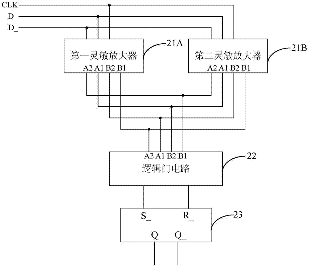
[0019] The embodiment of the present invention stores the data in different nodes through two-way interlocking, performs anti-single event flipping interference processing on the data of different nodes, generates a pre-charge signal, a set signal or a reset signal, and then performs logic operations on the data of different nodes. Anti-single-event upset processing, and no delay output through ...


PUM


Abstract

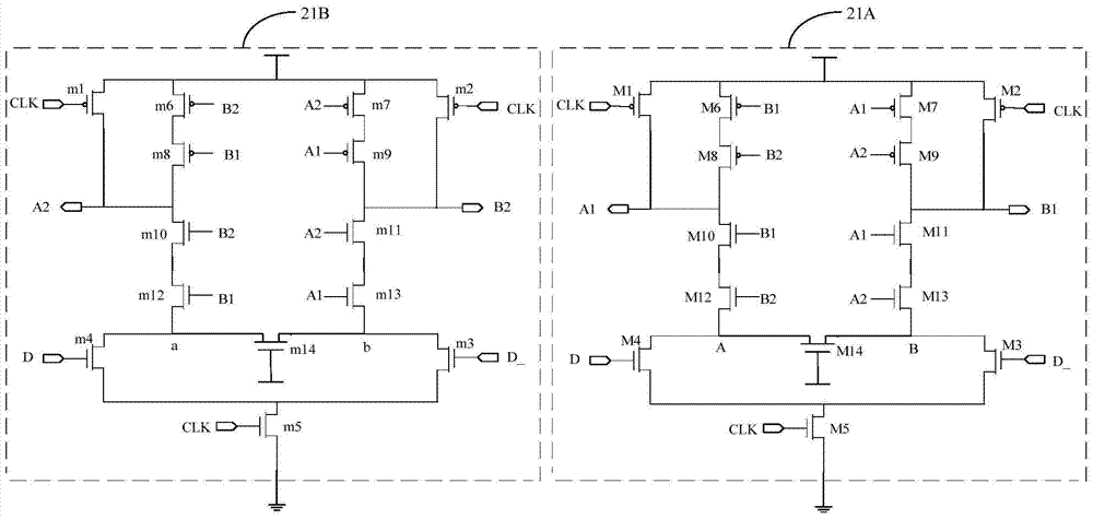
The invention is applicable to the field of integrated circuits, and provides an anti-radiation ultra-high-speed trigger circuit and an aerospace ultra-high-speed trigger. The circuit includes: first and second sensitive amplifiers with a double interlock structure, and data Stored in different nodes; logic gate circuits, perform anti-single event flip interference processing on data of different nodes, generate pre-charge signals, set signals or reset signals; RS latches with cross-coupling structure, when receiving pre-charge signals , forming an inverter pair structure to latch data, or when receiving a set signal or a reset signal, a symmetrical structure is used to realize output without delay. The present invention adopts two sensitive amplifiers of DICE structure as the front stage of the flip-flop to prevent the influence of SEU, and outputs the output of the front stage to the RS latch of the next stage after logic gate operation, through two symmetrical amplifiers with a cross-coupling structure The RS latch realizes the indiscriminate output of rising and falling edges, and realizes the function of disseminating data at a high speed.

Description

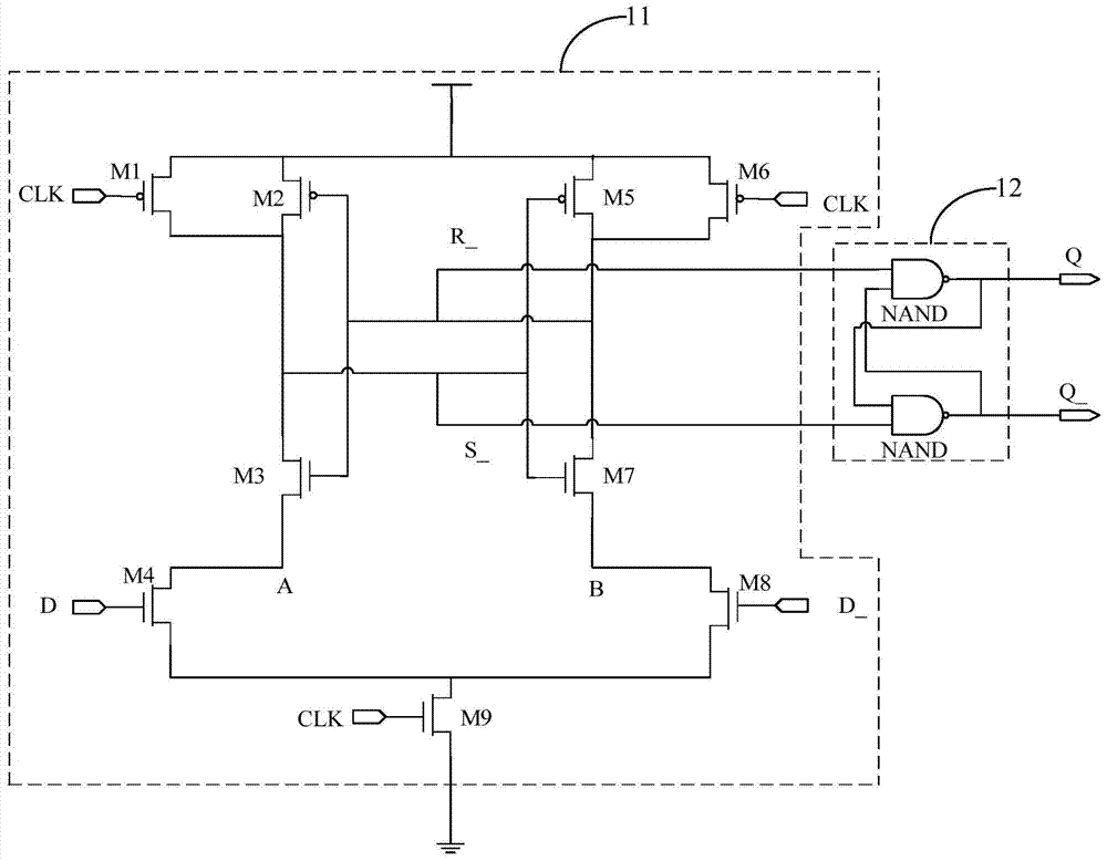
technical field [0001] The invention belongs to the field of integrated circuits, in particular to an anti-irradiation ultra-high-speed trigger circuit and an aerospace ultra-high-speed trigger. Background technique [0002] In modern integrated circuit design, flip-flops play an important role in the system, especially when flip-flops are used in aerospace equipment, in addition to more prominent performance requirements, there is also a very important point that requires sufficient resistance Irradiation capability, because in the space radiation environment, the device is easily affected by single event upset (SEU), which may affect the function of the device and output wrong data. [0003] At present, the flip-flop on the aerospace equipment generally adopts a flip-flop based on a sense amplifier (Sense-Amplifier-based Flip-Flop, SAFF), and the flip-flop based on a sense amplifier includes a latch-type sense amplifier 11 and an RS latch 12 Composition, the latch-type se...

Claims


Application Information

Patent Timeline
Patent Type & Authority Patents(China)
IPC IPC(8): H03K3/02
Inventor 宁源刘云龙孙博文李大超
Owner SHENZHEN STATE MICROELECTRONICS CO LTD
Learn More