Multifunctional insole and working method thereof

A multi-functional, insole technology, applied in the direction of insoles, footwear, clothing, etc., can solve the problems of unfavorable mass production and modular production assembly, difficult maintenance and replacement, high cost, etc., to facilitate modular production and mass assembly, increase Strength and durability, the effect of high power output

Pending Publication Date: 2018-03-02
ZHEJIANG UNIVERSITY OF MEDIA AND COMMUNICATIONS
View PDF11 Cites 5 Cited by
  • Summary
  • Abstract
  • Description
  • Claims
  • Application Information

AI Technical Summary

Problems solved by technology

[0004] The problems of the above-mentioned patent structure are: multiple gear sets are used for transmission, the structure is relatively complicated, and the cost is high; moreover, the transmission mechanism is arranged inside the casing, while the pressure plate is arranged outside the casing, and the two are arranged separately, occupying a large area of ​​the insole , which is not conducive to mass production and modular production assembly; the most important thing is that when the pressure plate is reset, there is a gap in which the mechanical energy disappears. In order to solve this problem, the patent sets an inertial compass on the rotating shaft of the micro-generator. In the absence of mechanical energy, the micro-generator remains in the state of power generation due to the rotation of the inertial compass. However, according to the law of energy conservation, this method has pr

Method used


Image

  • Multifunctional insole and working method thereof
  • Multifunctional insole and working method thereof
  • Multifunctional insole and working method thereof

Examples


Embodiment

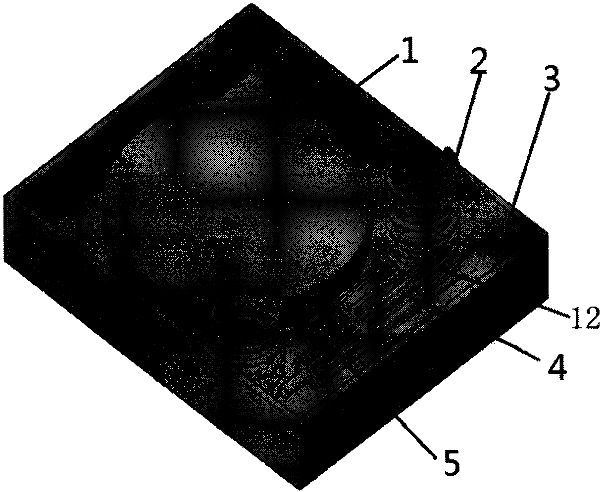
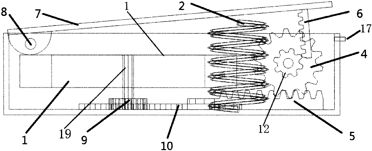
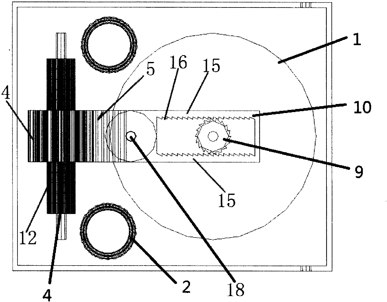
[0028] Embodiment: The description of the orientation in this embodiment is based on the description of the insole and the power generation device in normal use. Left and right are only relative orientations, not specific; Figure 1-6 As shown, a kind of multi-functional insole of the present embodiment comprises a shoe-pad body 21, and a power generating device 23 for converting kinetic energy of a person into electric energy when walking is arranged in the shoe-pad body 21, as shown in FIG. figure 1 As shown, the power generating device 23 includes a casing 3, and a pressure transmission mechanism, a rack transmission mechanism and a micro-generator 1 are arranged in the casing 3; figure 2 , 3As shown, the pressure transmission mechanism includes a pressure plate 7 arranged on the upper end of the housing 3 and a return spring 2 in the housing 1. One end of the pressure plate 7 is hinged to the housing 3 through a pin 8, and the other end of the pressure plate 7 is provided...


PUM


Abstract

The invention discloses a multifunctional insole and a working method. The multifunctional insole comprises a power generator which is provided with a shell, wherein a pressure transmission mechanism,a gear rack transmission mechanism and a micro generator are arranged in the shell; the pressure transmission mechanism comprises a pressing plate and a reset spring; one end of the pressing plate ishinged with the shell, and the other end of the pressing plate is provided with a pressure transmission gear rack downwards; the gear rack transmission mechanism comprises a ratchet wheel, a ratchetplate, a gear transmission gear rack as well as a small gear and a big gear; the small gear and the pressure transmission gear rack are meshed; the gear transmission gear rack and the ratchet plate are in rotatable connection; the gear transmission gear rack is meshed with the big gear; the ratchet plate comprises a ratchet plate main body and two ratchet racks; by virtue of the ratchet plate which is driven by the back-and-forth moving of the gear transmission gear rack, two ratchet racks are meshed with the ratchet; the ratchet is connected to a motor shaft of the micro generator; and a wireinterface is connected to the micro generator. According to the multifunctional insole provided by the invention, the racket, which is constantly acted during walking of a user, is rotated in one direction, so that power generation of the micro generator is promoted and relatively high power output is kept.

Description

technical field [0001] The invention relates to an insole, in particular to a multifunctional power generation insole, which is especially suitable for charging small electronic devices. Background technique [0002] Shoes are indispensable to people's lives, and their main purpose is to walk. Along with the raising of people's living standard, various shoes are designed, as air-cushioned shoes, non-slip shoes. [0003] There are very few shoes or insoles that can store electricity in current life. Especially in some special occasions such as field activities, people often find that some small electrical appliances such as mobile phones cannot be effectively charged in time; thus the Chinese patent No. "CN200520073075. Insole”, the patent aims to realize power generation through the following method: when people walk, they step on the pressure plate in the insole with their heels, and the pressure plate drives the seesaw to rotate downwards, so that the gear on the seesaw ...

Claims


Application Information

Patent Timeline
IPC IPC(8): A43B7/04A43B17/00A43B3/35
CPCA43B17/00A43B3/35
Inventor 项铭姜燕冰陈华锋金步平梅振林张解放张燕华
Owner ZHEJIANG UNIVERSITY OF MEDIA AND COMMUNICATIONS
Why Eureka
Try Eureka