
An oil drum handle installation device

A technology for installing equipment and oil drums, applied in metal processing equipment, metal processing, manufacturing tools, etc., can solve the problems of heavy repetitive labor and low labor productivity

Active Publication Date: 2019-04-26
南通埃东石化设备制造有限公司
View PDF6 Cites 0 Cited by
  • Summary
  • Abstract
  • Description
  • Claims
  • Application Information

AI Technical Summary

Problems solved by technology

However, the installation of the general 5L oil drum handle is manual installation, and the repetitive labor workload is large and the labor productivity is low in the production process.

Method used


Image

  • An oil drum handle installation device
  • An oil drum handle installation device
  • An oil drum handle installation device

Examples


Embodiment Construction

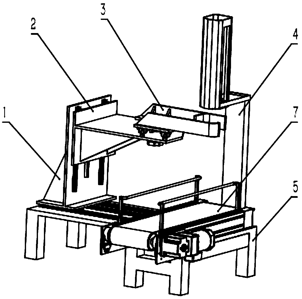
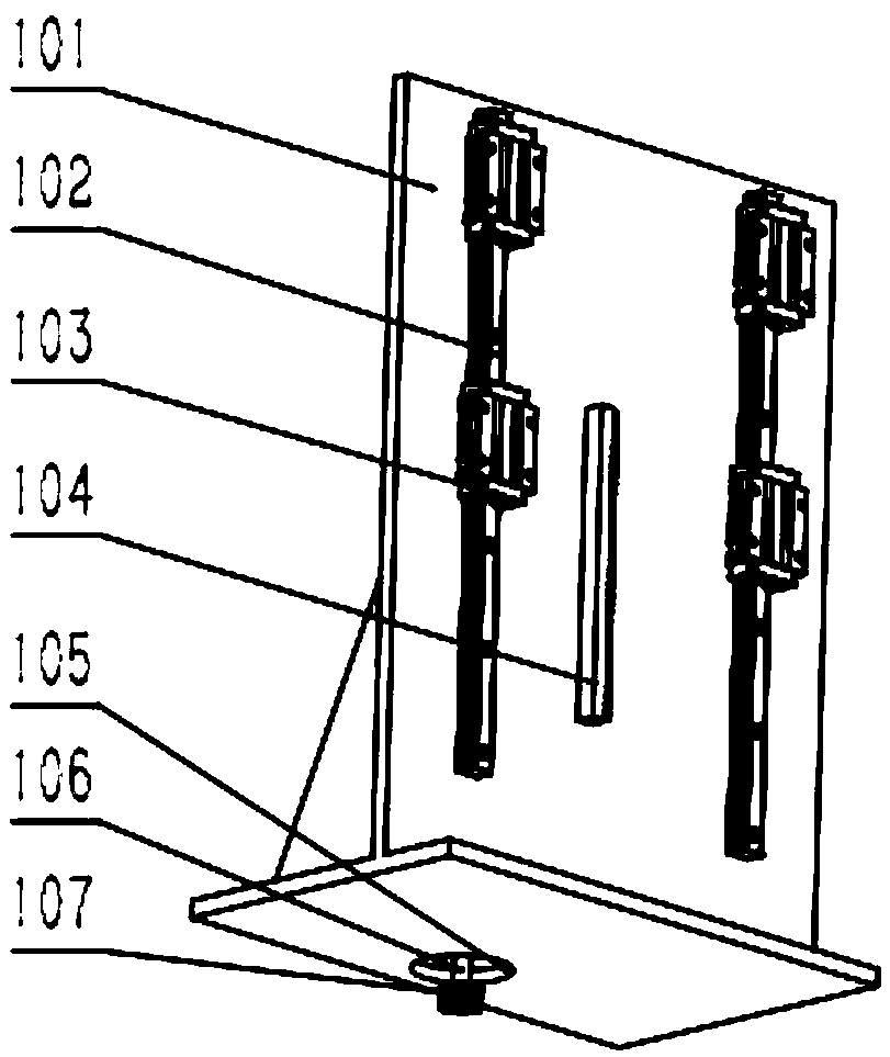
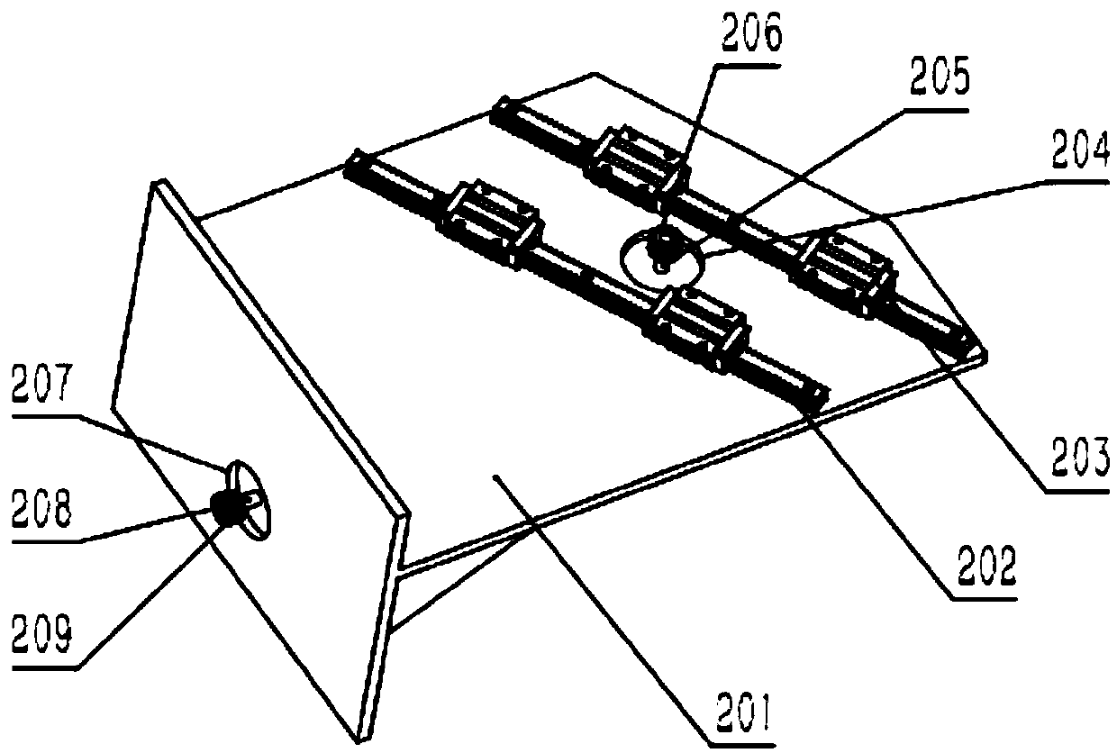
[0018] An oil drum handle installation device is composed of a Z-direction pallet assembly 1, a Y-direction pallet assembly 2, a manipulator assembly 3, an oil drum handle placement assembly 4, a base support assembly 5, and a conveyor belt assembly 7. The pallet assembly 1 is installed on the base support assembly 5, the Y-direction pallet assembly 2 is installed on the Z-direction pallet assembly 1, the manipulator assembly 3 is installed on the Y-direction pallet assembly 2, and the oil drum handle placement assembly 4 is fixed On the base support assembly 5 , the conveyor belt assembly 7 is fixed on the base support assembly 5 .

[0019] The base support assembly 5 is composed of a support frame 501, an X-direction rail 502, an X-direction slider 503 and an X-direction rack 504, two X-direction rails 502 are fixed on the support frame 501 in parallel, and four X-direction sliders 503 are installed on two X-direction rails 502 respectively, and X-direction rack 504 is fixed...


PUM


Abstract

The invention discloses oil drum carrying handle mounting equipment and belongs to the field of production and machining equipment. The oil drum carrying handle mounting equipment consists of a Z-direction supporting plate assembly, a Y-direction supporting plate assembly, a manipulator assembly, an oil drum carrying handle containing assembly, a base supporting assembly and a conveying belt assembly. The oil drum carrying handle mounting equipment is characterized in that the Z-direction supporting plate assembly is arranged on the base supporting assembly; the Y-direction supporting plate assembly is arranged on the Z-direction supporting plate assembly; the manipulator assembly is arranged on the Y-direction supporting plate assembly; the oil drum carrying handle containing assembly isfixed to the base supporting assembly; and the conveying belt assembly is fixed to the base supporting assembly. A manipulator arranged on the oil drum carrying handle mounting equipment has a centering function, and the manipulator can take a drum conveniently; by replacing an oil drum carrying handle containing groove, the mounting of other different types of oil drum carrying handles can be completed; and the oil drum carrying handle mounting equipment is high in automation degree and can meet the mounting work of the different types of oil drum carrying handles, and the production efficiency is improved.

Description

technical field [0001] The invention relates to a device for installing a handle for an oil drum, in particular to an automatic device for realizing the installation of a handle for an oil drum by using the conveying function of a manipulator and the conveying function of a conveyor belt, and belongs to the field of production and processing equipment. Background technique [0002] With the expansion of production scale, the increase of social material wealth, the high development of robot and automation equipment industry, robot automation production line has formed a huge manufacturing industry. And now the installation of the general 5L oil drum handle is manually installed, and the repetitive labor workload is large and the labor productivity is low in the production process. Therefore, under the impetus of social productivity, it is of great significance to design an oil drum handle installation equipment that can liberate workers' labor force and improve labor producti...

Claims


Application Information

Patent Timeline
Patent Type & Authority Patents(China)
IPC IPC(8): B23P19/00
CPCB23P19/001
Inventor 王一彩王兴雷李兰香刘飞月程澄
Owner 南通埃东石化设备制造有限公司
Learn More