Efficient cooling forming fiber spinneret plate

A technology of cooling forming and spinneret, which is applied in the direction of spinneret assemblies, textiles and papermaking, etc., to achieve the effects of increasing outflow rate, improving cooling timeliness, and improving cooling uniformity

Inactive Publication Date: 2018-03-02
SUZHOU DONGSHENG CHEM FIBER TEXTILE
View PDF0 Cites 2 Cited by
  • Summary
  • Abstract
  • Description
  • Claims
  • Application Information

AI Technical Summary

Problems solved by technology

[0003] The technical problem mainly solved by the present invention is to provide a high-efficiency cooling forming fiber spinneret, which can solve the above-mentioned problems existing in the existing spinneret

Method used


Image

  • Efficient cooling forming fiber spinneret plate
  • Efficient cooling forming fiber spinneret plate

Examples


Embodiment 1

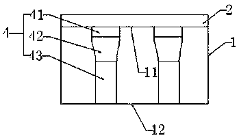
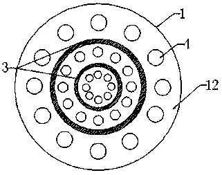
[0017] A high-efficiency cooling molding fiber spinneret, including a spinneret body 1, a filter screen 2 and a cooling system 3; wherein, the spinneret body 1 is a cylinder, and the filter screen 2 is embedded and fixed on the spinneret body 1, the filter screen is a detachable double-layer structure, and its outer aperture is twice that of the inner aperture. When a certain amount of impurities are intercepted on the outer side of the filter screen, the outer filter screen can be disassembled and cleaned directly. , which can reduce the cleaning frequency of the inner filter, reduce the cleaning difficulty of the filter as a whole, and improve the filtering quality.

[0018] The spinneret body 1 is provided with spinneret holes 4 arranged at regular intervals, which are distributed in a ring around the center of the spinneret body 1 , and the distance between the spinneret holes between adjacent rings is 3-10 mm. The spinneret hole 4 runs through the spinneret body 1, and it...

Embodiment 2

[0022] The difference from Example 1 is that the length ratio of the feed section 41 , the middle section 42 and the discharge section 43 on the spinneret body 1 is 1.5:3:5.

[0023] The diameter of the outer aperture is three times that of the inner aperture.

[0024] The diameter of the spinneret hole 4 is set as follows: the diameters of the spinneret holes on the same ring are the same, and the diameters of the spinneret holes on each ring from the center of the spinneret body 1 to the edge increase in an arithmetic sequence, And the tolerance is 3 μm, and the minimum diameter of the spinneret hole near the center is 3 μm.

[0025] The design of the spinneret hole of the present invention, on the one hand, improves the shaping effect of the fiber filament and increases its tensile strength; on the other hand, it effectively improves the outflow efficiency of the fiber mucus, avoids mucus retention, and improves the outflow rate; the design of the cooling system The coolin...


PUM

PropertyMeasurementUnit
diameteraaaaaaaaaa

Abstract

The invention discloses a high-efficiency cooling molding fiber spinneret, which includes a spinneret body, a filter screen and a cooling system; wherein, the spinneret body is a cylinder, and the filter screen is embedded and fixed on the spinneret The feeding surface of the body; the spinneret body has spinneret holes distributed in an orderly interval, the spinneret holes are distributed in a ring around the center of the spinneret body, and the cooling system is installed on the on the spinneret body, and embedded between the spinneret holes distributed between adjacent rings. On the one hand, the mechanism design of the spinneret hole of the present invention improves the shaping effect of the fiber filament and increases its tensile strength; on the other hand, it effectively improves the outflow efficiency of the fiber mucus, avoids mucus retention, and improves the outflow rate; The design improves the cooling uniformity and cooling timeliness of the fiber filaments, and the resulting fiber filament structure and performance are excellent.

Description

technical field [0001] The invention relates to the field of fiber production equipment, in particular to a high-efficiency cooling forming fiber spinneret. Background technique [0002] The spinneret, also known as the spinning cap, is used to transform the viscous polymer melt or solution through the micropores into a thin stream with a specific cross-section, and to form a filament after being solidified by a coagulation medium such as air or a coagulation bath. strip. The existing spinneret has the following problems in the actual use process: 1. The spinneret channel of the spinneret or the structure is single, so that the fiber filaments are quickly shaped at the exit, the shaping effect is not good, the forming degree is insufficient, and the tensile properties Insufficient; or the spinneret channel is particularly complicated, not only inconvenient to prepare, but also easy to reduce the melt flow rate and affect the spinneret speed, and it is easy to retain the spi...

Claims


Application Information

Patent Timeline
Patent Type & Authority Applications(China)
IPC IPC(8): D01D4/00D01D4/02
CPCD01D4/00D01D4/02
Inventor 宋建东
Owner SUZHOU DONGSHENG CHEM FIBER TEXTILE
Why Eureka
Try Eureka