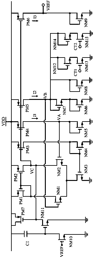
Reference circuit structure in voltage stabilizing system
A reference circuit and circuit technology, which can be used in control/regulating systems, regulating electrical variables, instruments, etc., and can solve problems such as high power consumption and large chip area.
- Summary
- Abstract
- Description
- Claims
- Application Information
AI Technical Summary
Problems solved by technology
Method used
Image
Examples
Embodiment Construction
[0013] combine figure 1 As shown, in the following embodiments, the reference circuit structure in the voltage stabilizing system at least includes: a start-up circuit that drives the reference circuit through a single NMOS transistor; an operational amplifier circuit that adopts a self-biased differential structure , to minimize the impact of current changes on the circuit; a core reference circuit, the accuracy of the reference current and reference voltage generated is very high, and the temperature coefficient can be adjusted according to the actual test situation. Since the entire circuit does not use resistors, No triode is used either, so the overall circuit area is also very small. For the voltage regulation system, the reference circuit with low power consumption is very advantageous.
[0014] The start-up circuit is composed of capacitor C1, NMOS tubes NM10 and NM11. When the power supply VDD is powered on, the voltage across the capacitor C1 will not change suddenl...
PUM
 Abstract
Description
Claims
Application Information
 - R&D
- Intellectual Property
- Life Sciences
- Materials
- Tech Scout
- Unparalleled Data Quality
- Higher Quality Content
- 60% Fewer Hallucinations
Browse by: Latest US Patents, China's latest patents, Technical Efficacy Thesaurus, Application Domain, Technology Topic, Popular Technical Reports.
© 2025 PatSnap. All rights reserved.Legal|Privacy policy|Modern Slavery Act Transparency Statement|Sitemap|About US| Contact US: help@patsnap.com

