Pump coupling device and manufacturing method

A technology of a pump coupling device and a manufacturing method, which is applied to laser parts, electrical components, active medium materials, etc., can solve problems such as the influence of the output light beam quality and the complex coating process of the spectroscope, so as to improve the absorption efficiency and increase the transmission. effect of length

Inactive Publication Date: 2018-03-02
11TH RES INST OF CHINA ELECTRONICS TECH GROUP CORP
View PDF3 Cites 3 Cited by
  • Summary
  • Abstract
  • Description
  • Claims
  • Application Information

AI Technical Summary

Problems solved by technology

However, the coating process of the beam splitter is relatively complicated. Under the condition of high power operation, due to the thermal effect of the beam splitter itself, the quality of the output light beam may be affected.

Method used


Image

  • Pump coupling device and manufacturing method
  • Pump coupling device and manufacturing method
  • Pump coupling device and manufacturing method

Examples


no. 1 example

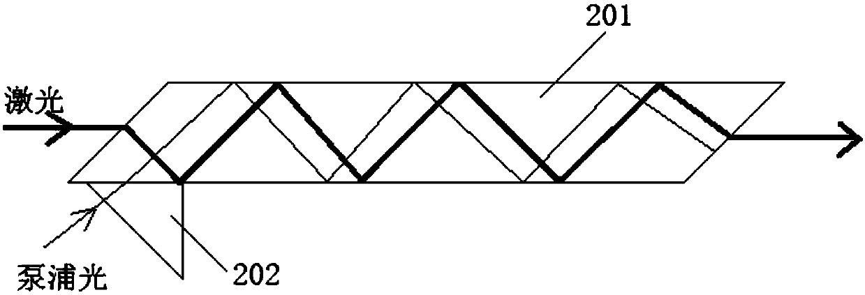
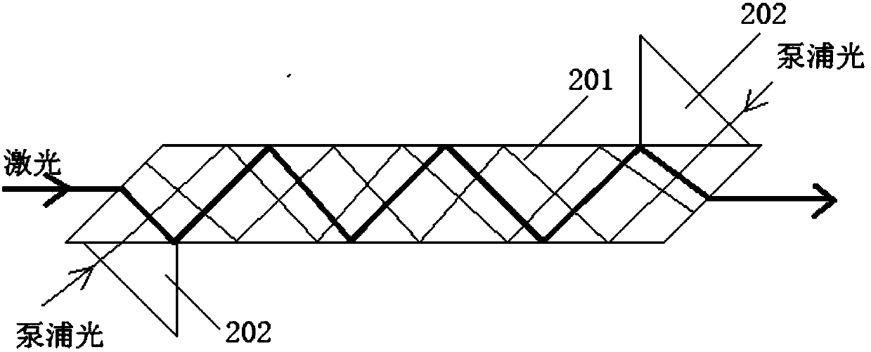
[0032] In the first embodiment of the present invention, a pump coupling device is applied to lasers, such as figure 2 As shown, the device specifically includes the following components: a gain medium slab 201, and a refractor 202;

[0033] The refractor 202 is bonded to the upper surface and / or the lower surface of the gain medium slab 201, and the refractor 202 is located at the position where the pump light enters the gain medium slab 201;

[0034] The gain medium slab 201 is used to transmit laser light; the slab acts as a laser gain medium.

[0035] The refractor 202 is used to guide the pump light into the gain medium slab 201 , so that the transmission path of the pump light in the gain medium slab 201 is different from the transmission path of the laser light in the gain medium slab 201 .

[0036] Specifically, the gain medium slab 201 is a gain medium plate of Nd:YAG-YAG-Nd:YAG structure composed of one yttrium aluminum garnet YAG ceramic blank and two neodymium-do...

no. 2 example

[0046] In the second embodiment of the present invention, a method for manufacturing a pump coupling device, such as Figure 4 As shown, the method specifically includes the following steps:

[0047] Step S401 : using one YAG YAG ceramic blank and two Nd-doped YAG Nd:YAG ceramic blanks to prepare Nd:YAG-YAG-Nd:YAG gain medium slats.

[0048] Specifically, step S401 includes:

[0049] Prepare one piece of YAG ceramic blank and two pieces of Nd:YAG ceramic blank that meet the requirements. The three blanks are directly pressed together, and then the blank is sintered according to the standard laser ceramic sintering process, and the Nd:YAG is thinned after forming. Ceramic part to desired thickness, fine polished,

[0050] Step S402: Cutting the two ends of the gain medium slab according to the Brinell angle.

[0051] The specific step S402 includes:

[0052] Cut ends to desired angle and desired slat length, finish polished.

[0053] Step S403: bonding a refractor on the upp...


PUM


Abstract

The invention discloses a pump coupling device and a manufacturing method. The device comprises a gain medium lath and a refractile body. The refractile body is bonded to an upper surface and/or a lower surface of the gain medium lath. The refractile body is located at a position where pump light is emitted into the gain medium lath. The gain medium lath is used for transmitting laser. The refractile body is used for guiding the pump light into the gain medium lath so that a transmission path of the pump light in the gain medium lath is different from a transmission path of the laser in the gain medium lath. In the invention, a spectroscope is avoided to be used to affect output laser beam quality, and a different optical-path transmission mode of the pump light and the laser is adopted sothat the pump light and the laser can be effectively separated.

Description

technical field [0001] The invention relates to the technical field of solid-state lasers, in particular to a pump coupling device and a manufacturing method thereof. Background technique [0002] All-solid-state lasers with high power and high beam quality have always been a research hotspot in the laser field, and have important applications in industry, national defense, medical treatment, environmental protection and scientific research. Due to the shape of the gain medium in the traditional solid-state laser, there is a serious thermal effect inside it, which limits the laser output with high power and high beam quality. For the slab laser, since the temperature gradient only occurs in the thickness direction of the slab, the zigzag transmission of the laser in the gain medium can just compensate for it, and obtain a laser output with high power and high beam quality. [0003] The slabs used in the early days were thicker. With the development of optical processing tec...

Claims


Application Information

Patent Timeline
Patent Type & Authority Applications(China)
IPC IPC(8): H01S3/094H01S3/16
CPCH01S3/094049H01S3/1611H01S3/1643
Inventor 王超刘洋王文涛王喆唐晓军刘娇
Owner 11TH RES INST OF CHINA ELECTRONICS TECH GROUP CORP
Why Eureka
Try Eureka