Spiral-flow type water-soluble fertilizer fertilization tank
A technology of water-soluble fertilizer and fertilization tank, which is applied in fertilization devices, liquid fertilizer distribution, and manure treatment, etc., can solve the problems of different fertilizer quality, time-consuming and labor-intensive, etc., so as to promote the mixing reaction, the stirring is sufficient and rapid, and the concentration difference is avoided. uniform effect
- Summary
- Abstract
- Description
- Claims
- Application Information
AI Technical Summary
Problems solved by technology
Method used
Image
Examples
Embodiment 1
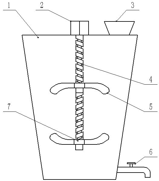
[0020] A swirling water-soluble fertilizer fertilization tank, comprising a tank body 1, a feed port 3, a discharge port 6 and a stirring device; the feed port 3 is arranged above the tank body 1; the discharge port 6 is arranged below the tank body 1; the stirring device is arranged inside the tank body 1; the stirring device includes a stirring shaft 4 and a stirring paddle 5; the outer wall of the stirring shaft 4 is provided with a thread groove The stirring paddles 5 are axially arranged in two layers along the stirring shaft 4; the stirring paddles 5 are all connected to the stirring shaft 4 through the connector 7; , the motor 2 is connected to the stirring shaft 4. The connecting piece 7 is a sleeve provided with an internal thread; the internal thread matches the thread groove on the stirring shaft 4; the stirring paddle 5 is installed on the outer wall of the sleeve.
[0021] The stirring shaft 4 is divided into upper and lower sections, and each section of the stir...
Embodiment 2
[0024] A swirling water-soluble fertilizer fertilization tank includes a tank body 1, a feed inlet 3, a discharge outlet 6 and a stirring device; the tank body 1 is an inverted cone. The feed inlet 3 is arranged above the tank body 1; the discharge outlet 6 is arranged below the tank body 1; the stirring device is arranged inside the tank body 1; the stirring device includes a stirring Shaft 4 and stirring paddle 5; The outer wall of described stirring shaft 4 is provided with threaded groove; Described stirring paddle 5 is arranged in upper and lower layers along the axial direction of stirring shaft 4; Described stirring paddle 5 passes through The connecting piece 7 is connected to the stirring shaft 4; the motor 2 is arranged above the tank body 1, and the motor 2 is connected to the stirring shaft 4. The connecting piece 7 is a sleeve provided with an internal thread; the internal thread matches the thread groove on the stirring shaft 4; the stirring paddle 5 is installed...
PUM
 Abstract
Description
Claims
Application Information
 - R&D
- Intellectual Property
- Life Sciences
- Materials
- Tech Scout
- Unparalleled Data Quality
- Higher Quality Content
- 60% Fewer Hallucinations
Browse by: Latest US Patents, China's latest patents, Technical Efficacy Thesaurus, Application Domain, Technology Topic, Popular Technical Reports.
© 2025 PatSnap. All rights reserved.Legal|Privacy policy|Modern Slavery Act Transparency Statement|Sitemap|About US| Contact US: help@patsnap.com

