Rotational fluidized bed powder mixing machine

A technology of mixer and fluidized bed, which is applied in the field of powder particle material mixing equipment, can solve the problem that the structural form is not as diverse as that of mechanical mixing equipment, and achieve the effect of simple equipment structure, low air consumption, and guaranteed mixing quality

Inactive Publication Date: 2018-03-06
CHANGZHOU UNIV
View PDF6 Cites 3 Cited by
  • Summary
  • Abstract
  • Description
  • Claims
  • Application Information

AI Technical Summary

Problems solved by technology

Although airflow mixing equipment can make up for some shortcomings of mechanical mixing equipment, compared with mechanical mixing equipment, the current research and analysis on airflow mixing equipment is far less detailed than mechanical mixing equipment, and its structure is far less than mechanical mixing equipment. The structure of the equipment is diverse, and these problems need to be solved in order to obtain an airflow powder mixing equipment with a higher mixing effect

Method used


Image

  • Rotational fluidized bed powder mixing machine
  • Rotational fluidized bed powder mixing machine

Examples


Embodiment Construction

[0010] The present invention will be further described in detail below in conjunction with the accompanying drawings and specific embodiments. The drawings and specific embodiments do not limit the scope of protection claimed by the present invention.

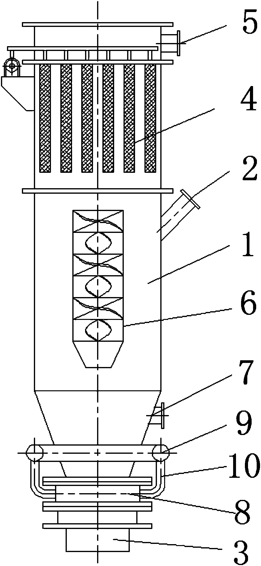
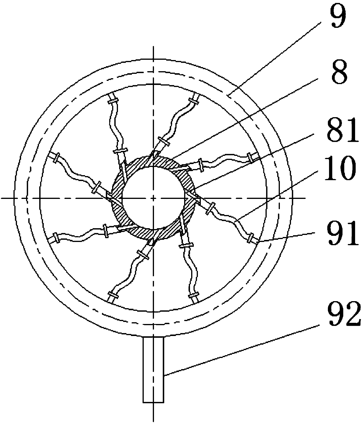
[0011] see figure 1 As shown in the rotary fluidized bed powder mixer of the present invention, its main body is the mixing silo cylinder 1, which is generally made of stainless steel and can be coated according to special needs. The side of the mixing silo body 1 is provided with a powder particle material feed port 2 and a sampling port 7, an exhaust port 5 is provided at the top, and a material outlet 3 is provided at the bottom. A static mixer 6 is arranged inside, and left-handed unit pieces and right-handed unit pieces are alternately arranged inside the static mixer 6, and the number of unit pieces can be set to 6-10. The upper part of the mixing silo body 1 is a pulse bag filter 4 for filtering exhaust gas. The botto...


PUM


Abstract

The invention discloses a rotational fluidized bed powder mixing machine which comprises a material mixing cabin body, a material inlet, a material outlet, a bag type dust collector and a sampling hole, wherein a static mixer is mounted inside the material mixing cabin body; rotational flow nozzles are mounted at the bottom of the material mixing cabin body; and the rotational flow nozzles are connected with an air flow distributor. When the machine is used, continuous air flow is fed into the material mixing cabin body through the rotational flow nozzles, then a rotational fluidized bed layeris formed, granular materials are driven to turn over up and down, powder granular materials can be relatively intensely mixed in the lifting and dropping process through the static mixer inside thematerial mixing cabin body, and a very good mixing effect is achieved within a short time. The rotational fluidized bed powder mixing machine is relatively simple in structural mode and simple and convenient to operate and maintain, and the mixing quality of different batches of powder granular materials can be ensured with relatively low air consumption within a relatively short mixing time.

Description

Technical field: [0001] The invention relates to a powder particle material mixing device, in particular to a rotary fluidized bed powder mixing device. Background technique: [0002] For different batches of powder particles, mechanical stirring or fluid drive can be used, so that two or more powder particles can be uniformly distributed in each position, thus ensuring the high quality of the product. Because there are no parts that need to be rotated inside the airflow powder mixing equipment, compared with the commonly used mechanical stirring powder mixing equipment, it has a series of advantages of less complicated structure and relatively less maintenance and repair. At the same time, because the airflow is used to drive the powder for mixing, there are no stirring parts like stirring paddles, which avoids the wear and tear of mechanical powder mixing equipment due to the high-speed rotation of the paddles and the possible coating peeling off of the paddles due to high...

Claims


Application Information

Patent Timeline
Patent Type & Authority Applications(China)
IPC IPC(8): B01F3/18B01F13/02B01F33/40
CPCB01F23/60B01F33/406B01F33/4094
Inventor 刘雪东陈程刘文明郑瑜
Owner CHANGZHOU UNIV
Why Eureka
Try Eureka